PERKO 1617 User Manual
PERKO Lighting
Cat. No. 1616 & 1618 Series
Stealth L.E.D. Bi-Color Lights
Patent Pending
The above lights are designed for use on power driven vessels under 12 meters (39.4 ft.)
in length operating on a nominal 12 volt system. Each pole light must be used with a
separately mounted base. When properly installed these replacement poles will comply
with the '72 COLREGS and the U.S. Inland Rules.
MOUNTING INFORMATION
Read all instructions before proceeding.
1). For information on proper light selection, positioning and configuration, refer to
A.B.Y.C. Standard A-16 (1), the '72 COLREGS, and the U.S. Inland Rules (2).
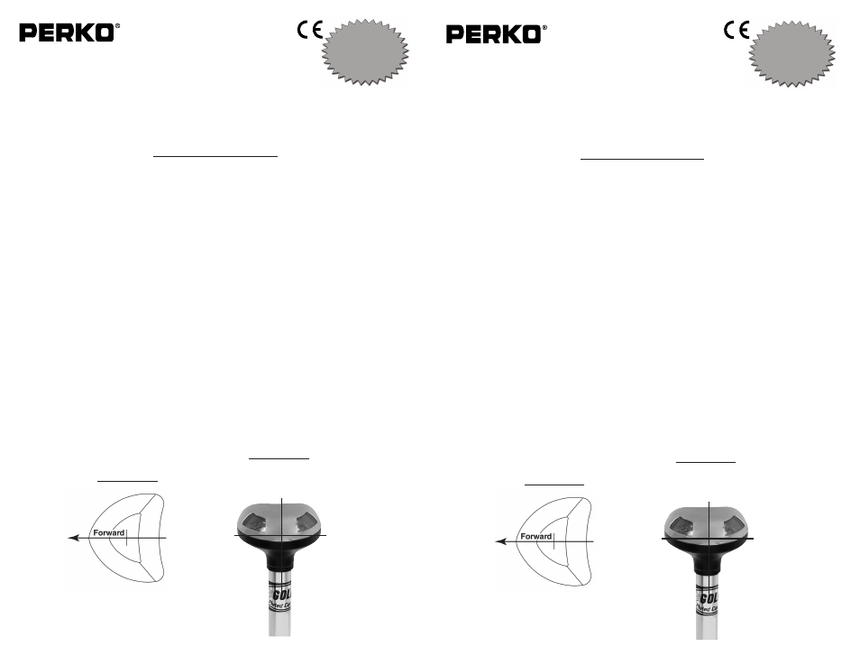
2). IMPORTANT: Top of light must be vertical during operation (See Diagram #2). If
base (installed separately) was properly orientated then front of the light will face
forward and parallel to the centerline of the boat. (See Diagram #1).
3). Setup for Operation:
Fig. 1616, Insert pole in base, making sure alignment screw in pole slides into
notch in base. Push pole down until it engages the electrical connector and then
lock by rotating the locking collar clockwise.
Fig. 1618, As pole engages with base, make sure alignment screw in pole slides
into the notch in the base. Push the pole until it engages the electrical connector.
Turn the threaded collar clockwise until it threads into place and is snug onto the
base.
4). These lights use L.E.D.s and therefore are not serviceable. Do not attempt to open
the lens cover.
5). L.E.D. lights are polarity sensitive. If the light does not operate after installation the
base wiring may need to be reversed. Remove the base and reverse the wire con-
nections.
(1) American Boat & Yacht Council, Inc.
(2) U.S. Coast Guard
613 Third Street, Suite 10
Washington D.C. 20593
Annapolis, MD 21403
(or your local C.G. Office)
PERKO, Inc.
16490 N.W. 13th Avenue
Miami, FL 33169-5707
www.perko.com
12/08
1616INS1
USCG
APPROVAL
33 CFR 183.810
Visibility: 1nm
Tested By: IMANNA Labs.
Date: 4/22/08
Meets ABYC A-16
Figs. 1616 & 1618
DIAGRAM #2
NOTE: Top of light must be
vertical during operation.
DIAGRAM #1
Cat. No. 1616 & 1618 Series
Stealth L.E.D. Bi-Color Lights
Patent Pending
The above lights are designed for use on power driven vessels under 12 meters (39.4 ft.)
in length operating on a nominal 12 volt system. Each pole light must be used with a
separately mounted base. When properly installed these replacement poles will comply
with the '72 COLREGS and the U.S. Inland Rules.
MOUNTING INFORMATION
Read all instructions before proceeding.
1). For information on proper light selection, positioning and configuration, refer to
A.B.Y.C. Standard A-16 (1), the '72 COLREGS, and the U.S. Inland Rules (2).
2). IMPORTANT: Top of light must be vertical during operation (See Diagram #2). If
base (installed separately) was properly orientated then front of the light will face
forward and parallel to the centerline of the boat. (See Diagram #1).
3). Setup for Operation:
Fig. 1616, Insert pole in base, making sure alignment screw in pole slides into
notch in base. Push pole down until it engages the electrical connector and then
lock by rotating the locking collar clockwise.
Fig. 1618, As pole engages with base, make sure alignment screw in pole slides
into the notch in the base. Push the pole until it engages the electrical connector.
Turn the threaded collar clockwise until it threads into place and is snug onto the
base.
4). These lights use L.E.D.s and therefore are not serviceable. Do not attempt to open
the lens cover.
5). L.E.D. lights are polarity sensitive. If the light does not operate after installation the
base wiring may need to be reversed. Remove the base and reverse the wire con-
nections.
(1) American Boat & Yacht Council, Inc.
(2) U.S. Coast Guard
613 Third Street, Suite 10
Washington D.C. 20593
Annapolis, MD 21403
(or your local C.G. Office)
PERKO, Inc.
16490 N.W. 13th Avenue
Miami, FL 33169-5707
www.perko.com
12/08
1616INS1
USCG
APPROVAL
33 CFR 183.810
Visibility: 1nm
Tested By: IMANNA Labs.
Date: 4/22/08
Meets ABYC A-16
Figs. 1616 & 1618
DIAGRAM #2
NOTE: Top of light must be
vertical during operation.
DIAGRAM #1