PERKO 1470 User Manual
Delta, Alpha, Series
CAT. NOS. 1400, 1470 and 1451 SERIES
WHITE ALL-ROUND LIGHTS (ALL SIZES)
The Delta Series (Figure No. 1470 & 1451) lights are for use on power driven vessels
under 20 meters (65.6 ft.) in length operating on a nominal 12 volt system. The Alpha
Series (Figure No. 1400) lights are for use on sail or power driven vessels under 20
meters (65.6 ft.) in length operating on a nominal 12 volt system (See Diagram #1).
All must be used with a separately mounted base (such as PERKO figure numbers 1045,
1046, 1047, 1059 or 1060). When properly installed, these replacement poles will comply
with ‘72 COLREGS and the U. S. Inland Rules.
MOUNTING INFORMATION
(Read all instructions before proceeding.)
1). For information on proper light selection, positioning and configuration, refer to A.B.Y.C. Standard A-16 (1),
the ‘72 COLREGS, and the U.S. Inland Rules (2).
2). The center of the lens of white all-round pole lights must be located at least 1 meter (39.4") above the center
of the lenses of either the bi-color or the red and green side lights on the vessel. Be sure to use a light with a
sufficiently long pole to meet this requirement.
3). IMPORTANT: "Reduced Glare" globes (Delta Series lights) must be mounted so that they are aligned
horizontally when the boat is at rest in the water in a "static floating position". See Diagram #2 in order to
assure compliance with technical details of the regulation and employ the "Reduced Glare" feature of the
series optical system. To adjust horizontal position of globe, install pole light into base on boat while in its
static floating postion. Loosen setscrew at top of pole. Adjust position of globe (relative to water) so that it
is aligned horizontally. Tighten setscrew to hold globe in that position.
4). Changing globes: Both globes supplied with Delta Series lights are legal for use while underway and at
anchor. The black bottom globe provides reduced glare benefits and is preferable for use when underway.
The clear frosted bottom globe provides light into the cockpit and is preferable for use when supplemental
cockpit illumination is desired. The clear globe does not provide reduced glare benefits. If used while
underway, be sure drivers eyes are shielded from glare produced from the light. To change globes, hold pole
firmly to avoid stress on pole/base connection and simply unscrew globe. CAUTION: Illuminated globes can
get very hot. Use a glove or some other form of hand protection if changing globes while hot.
5). These replacement poles will fit a large number of base styles produced by various manufacturers. The
differences involve screw positions and the use of a collar. Before attempting to install poles, identify the style
of base currently on the boat. (See Back)
6). To store folding lights (Series 1451) grasp both sections of pole and push towards center coupling
(See Diagram #3). While pushing, rotate one end of pole until screw is positioned in open slot.
Gently pull poles apart until they are clear of each other, then fold one pole onto the other with wire
passing through slot. NOTE: The wire will remain connected to both poles and will be damaged if too much
pulling force is applied.
POLE LIGHT COLLAR & SCREW POSITION CONFIGURATIONS
USED IN COMMON BASE TYPE APPLICATIONS:
A). OLD STYLE PERKO BASES
Figure Nos. 1023 & 1026 (With Locking Ring on the Base)
One screw in bottom position. No Collar. Remove top screw and cover hole with silver
disk included in package.
B). CURRENT STYLE PERKO BASES WITH ECCENTRIC COLLARS
Perko Series 1045, 1046, 1047, 1059 & 1060 and Some Imported Bases
One screw in bottom position. Eccentric Collar (check base to determine collar type –
threaded or eccentric). Remove top screw and cover hole with silver disk included in
package.
C). CURRENT STYLE PERKO BASES WITH THREADED COLLARS
Perko series 1048 and special versions of Perko Series 1045 bases
One screw in bottom position. Threaded Collar (check base to determine collar type –
threaded or eccentric). Remove top screw and cover hole with silver disk included in
package. NOTE: spacer is needed under collar when light is used with special 1045
style base with threaded collar
D). MANY BASES MADE BY OTHER MANUFACTURERS
Determine screw position by inserting pole into base. Application may require one screw
in either the top or bottom position or it may require the use of both screws. Likewise,
the application may not require a collar or may require the use of a threaded or eccen-
tric collar. Fit pole into base to determine need. If necessary, move screw to correct pos-
tion. If a screw hole is left unused, cover the unused screw hole with the
silver colored self-adhesive disk included in the package.
Note: Relamp only with bulb type as marked on globe or inside fixture. For light Diagram #1, use
replacement bulbs PERKO Cat. No. 0337012DP 12V, 11W. For light Diagram #2, use replacement
bulbs PERKO Cat. No. 0338DP2CLR 12V, 9W.
(1)
American Boat & Yacht Council, Inc.
(2)
U.S. Coast Guard
613 Third Street, Suite 10
Washington D.C. 20593
Annapolis, MD 21403
(or your local C.G. Office)
PERKO, Inc.
16490 N.W. 13th Avenue
Miami, FL 33169-5707
12/08
www.perko.com
1470INS1
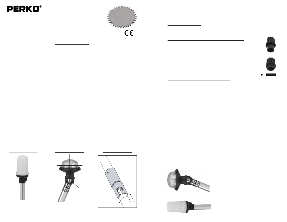
Note: Clear Globes
Must Be Vertical
During Operation.
DIAGRAM #1
DIAGRAM #3
Translucent
White
All-Round Light
USCG APPROVAL
33 CFR 183.810
Visibility: 2nm
Tested By: IMANNA Labs.
Date: 4/25/03
Meets ABYC A-16
DIAGRAM #2
Setscrew
Delta
Series
The
Ultimate
P
o
le
Light
Alpha
Series
The
Standard
in
Po
le
Lights
FIG.
1400
FIGS.
1470
& 1451
Optional Spacer