PERKO 1611 User Manual
Mounting template a, Cut out along broken line, Translucent white all-round light
Note: Clear Globes
Must Be
Vertical During
Operation.
CUT OUT ALONG BROKEN LINE
Cat. Nos.
1045P00DP
Fig. 1631 - (All Sizes)
Fig. 1632 - (All Sizes)
Fig. 1650 - (All Sizes)
MOUNTING TEMPLATE A
The above lights with clear globes (0238, 0239 & 0248) are designed for use on power driven vessels
under 20 meters (65.6 ft.) in length operating on a nominal 12 volt system. The above lights with
translucent globes (0201) are for use on sail or power driven vessels under 20 meters (65.6 ft.) in length.
In order to comply with ‘72 COLREGS and U.S. Inland Rules, the following must be adhered to:
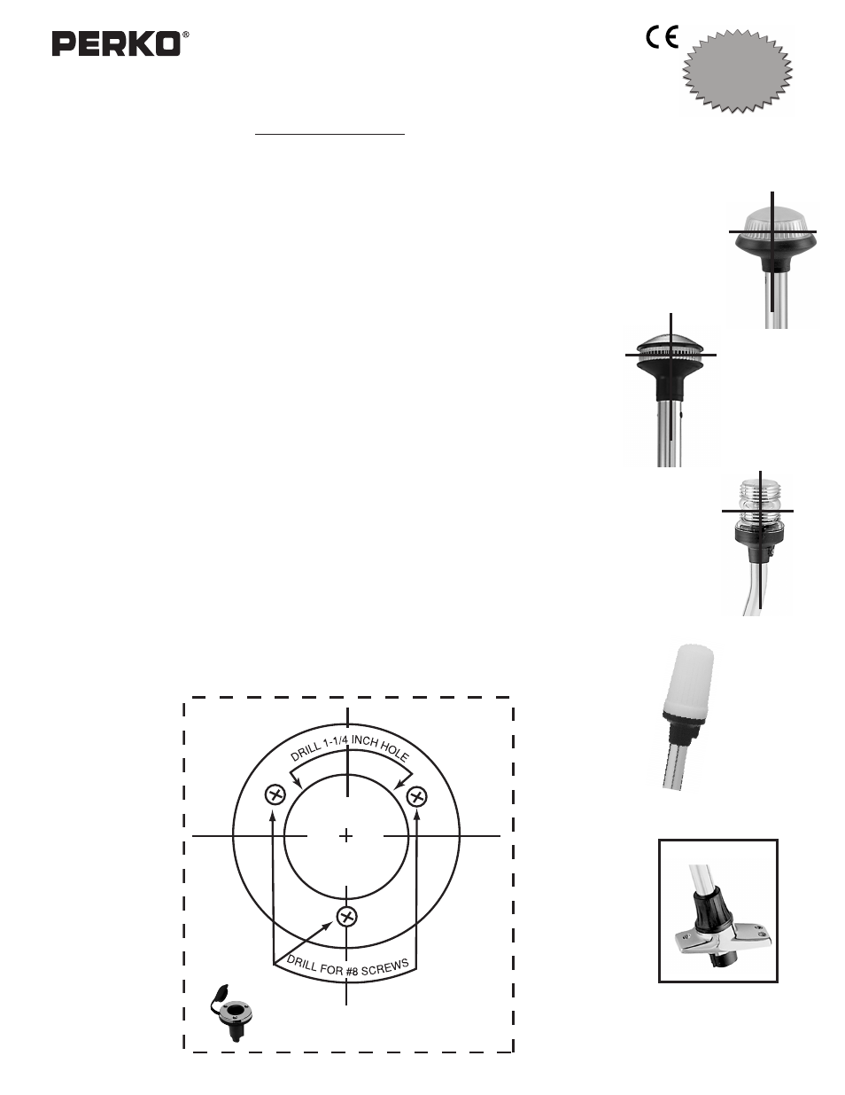
MOUNTING INFORMATION
Read all instructions before proceeding.
1).
For proper light selection, positioning and configuration, refer to A.B.Y.C. Standard A-16*,
‘72 COLREGS and U.S. Inland Rules*.
2).
These lights are designed to be mounted on a horizontal surface.
3).
For mounting template A, place a mark at the center of the selected mounting location. For templates
B& C, draw a 6 inch long reference line through the center of the selected mounting location and
parallel to the centerline of the boat.
4).
Cut out the appropriate mounting template. For template A, place it on the mounting surface such that
the reference mark (drawn above) is directly underneath the center of the template. For templates B &
C, place the template on the mounting surface such that the reference line drawn above is directly
underneath the reference line marked on the template.
5).
Drill indicated holes through the template to accommodate #8 oval head mounting screws and either
socket or telescopic poles as required.
6).
Attach supply connections to the light, making sure to wire in accordance with both A.B.Y.C. Standard
E-9* and U.S. Coast Guard Safety Standards for Boat Electrical Systems (33 CFR 183)*.
7).
Mount the base in accordance with the template.
8).
Important: Clear globes (0238, 0239 & 0248) must be vertical during operation in order to assure
compliance with the technical details of the regulations and employ the “Reduced Glare” feature of the
1431, 1632 & 1650 series optical systems.
9).
Set-up for Operation:
a). Plug-in Models: As pole engages with base, make sure alignment screw in pole slides into the notch
in the base. Push the pole until it engages the electrical connector. Turn the locking collar clockwise
until it drops into place and locks the pole. Clear globes must be vertical. (See Step #8).
b).Telescopic Models: Lock pole in fully extended position. The locking collar on the pole is eccentric and
is turned clockwise to lock and counterclockwise to unlock.
10). Relamp only with bulb type as marked on globe or inside fixture. For clear transparent globes (0248
Series 1311 & 1330 Lights) use ANSI #90 bulbs (PERKO Cat. No. 0337011DP 12V, 7W), for white
translucent globes (0201 Series 1430, 1611, 1630 & 1631 Lights) use ANSI #1004 Bulbs (PERKO Cat.
No. 0337012DP 12V, 11W), and for “Reduced Glare” Globes (0238 & Series 1431, 1632 & 1650 lights)
use ANSI #906 bulbs (PERKO Cat. No. 0338DP2CLR 12V, 9W).
* The above referenced standards can be obtained from:
(1) American Boat & Yacht Council, Inc.
(2) U.S. Coast Guard
613 Third Street, Suite 10
Washington, D.C. 20593
Annapolis, MD 21403
(or your local C.G. office)
Translucent
White
All-Round
Light
Collar in Locked Position
USCG APPROVAL
33 CFR 183.810
Visibility: 2nm
Tested By: IMANNA Labs.
Date: 2/4/03 & 4/25/03
Meets ABYC A-16
Globe 0248
Fig. 1311 & 1330
Globe 0201
Fig. 1611, 1430,
1630 & 1631
Globe 0238
“Reduced Glare”
Fig. 1431
& 1632
Globe 0239
“Reduced Glare”
Fig. 1650
Cat. Nos. 1311, 1330, 1430, 1431, 1611, 1630, 1631, 1632 & 1650 Series
White All-Round Lights (All Sizes)
12/08
1311INS1
PERKO, Inc.
16490 N.W. 13th Avenue
Miami, FL 33169-5707
www.perko.com