PERKO 1284 User Manual
PERKO Lighting
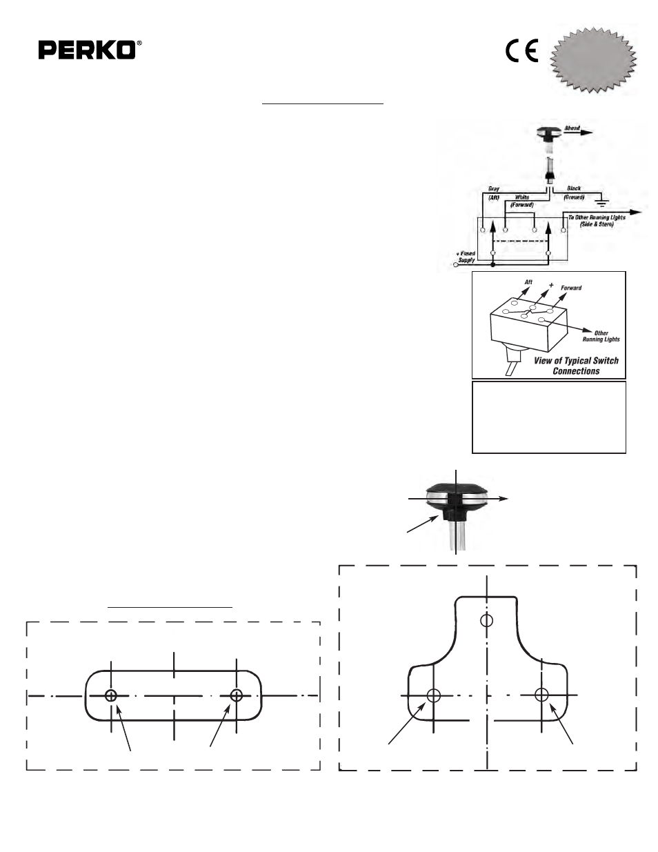
WIRING DIAGRAM FOR COMBINATION
MASTHEAD/ANCHOR LIGHTS
• Double pole, double throw switch
(center off)
• One position illuminates running
lights (masthead, side & stern)
• Other position illuminates anchor
light (forward & aft compartments
of combination masthead/anchor
light)
CUT ALONG BROKEN LINE
CUT ALONG BROKEN LINE
R
E
F
E
R
E
N
C
E
L
IN
E
REFERENCE LINE
CAT NOS. 1284000CHR
1284DP0CHR
CAT NOS. 1281000CHR
1281DP0CHR
DRILL FOR #8 SCREWS
DRILL FOR #8 SCREWS
DRILL FOR #8 SCREWS
MOUNTING TEMPLATES
AHEAD
NOTE: TOP OF LIGHT MUST BE
VERTICAL DURING
OPERATION
HOLDING
SCREW
USCG APPROVAL
33 CFR 183.810
Visibility: 2nm
Tested By: IMANNA Labs.
Date: 10/8/03
Meets ABYC A-16
Cat. No. 1281 Series Combination Masthead & All-Round (Anchor) Light
Cat. No. 1284 Series Combination Masthead & All-Round (Anchor) Light
The above lights are designed for use on power driven vessels under 12 meters (39.4 ft.) in length, operating on a nominal 12 volt
system. In order to comply with ‘72 COLREGS and the U.S. Inland Navigation Rules, the following must be adhered to:
MOUNTING INFORMATION
Read all instructions before proceeding.
1). These instructions show the orientation of the light after the proper mounting location has been determined.
For proper light selection, positioning and configuration, refer to A.B.Y.C. Standard A-16*, the 72 COLREGS*,
and the U.S. Inland Navigation Rules*. These lights are supplied complete with 12 volt bulbs
(Cat. No. 0338DP1CLR 12V, 5W).
2). These lights are designed to be mounted on a horizontal, vertical or angled surface. Adhere to instruction #8
below, while selecting the appropriate mounting surface.
3). a). Cat. No. 1281000CHR & 1281DP0CHR: Draw a 3 inch long reference line through the center of the
selected mounting location and parallel to the vertical plane through the fore-aft centerline of the boat.
b). Cat. No. 1284000CHR & 1284DP0CHR: Draw a 4 inch long reference line through the center of the
selected mounting location and parallel to the vertical plane through the fore-aft centerline of the boat.
4). Cut out the appropriate mounting template below. Tape it on to the mounting surface such that the reference
line (drawn above) is directly underneath the reference line marked on the template.
5). Drill indicated holes through the template to accommodate #8 oval head mounting screws.
6).
Attach supply connections to the light, making sure to wire in accordance with both A.B.Y.C. Standard E-9*
and U.S. Coast Guard Safety Standards for Boat Electrical Systems (33 CFR 183)*.
The supply leads are coded as follows:
WHITE:
Forward compartment (masthead light) positive supply lead.
RED or GRAY:
Aft compartment (when energized with the forward compartment: all-round light)
positive supply lead.
BLACK:
Negative supply lead. (CAUTION: Negative lead connected to case. To avoid
energizing case, observe polarity).
Electrical connections are to be made such that only the forward compartment (masthead light) is energized
with the other running lights (sidelights, stern light, etc.) while underway. Both compartments are energized
simultaneously by themselves to create the all-round (anchor) light. Be sure to use double-pole switches,
otherwise feedback will cause all lights in the system to be energized at the wrong time. See wiring diagram.
7). Mount the light in accordance with the template. A plastic mounting insulator (supplied) and stainless steel
fasteners may be used between the base and mounting surface to reduce the possibility of electrolysis on
dissimilar metals.
8). Make sure the top of the light is vertical during operation (see illustration), the arrow
on the top cover points ahead (not astern), and the reference marks are parallel to the fore-aft
centerline of the boat.
* The above referenced standards can be obtained from:
(1). American Boat & Yacht Council, Inc.
(2) U.S. Coast Guard
613 Third Street, Suite 10
Washington, D.C. 20593
Annapolis, MD 21403
(or your local C.G. office)
PERKO, INC.
16490 N.W. 13th Avenue
11/06
Miami, FL 33169-5707
1281INS1
www.perko.com