PERKO 1310 User Manual
PERKO Lighting
Cat. No. 1161 Series Bi-Color Light
Cat. No. 1310 Series Bi-Color Light
The above lights are designed for use on power driven vessels under 12 meters (39.4 ft.) in length, oper-
ating on a nominal 12 volt or 24 volt system. In order to comply with ‘72 COLREGS and the U.S. Inland
Navigation Rules, the following must be adhered to:
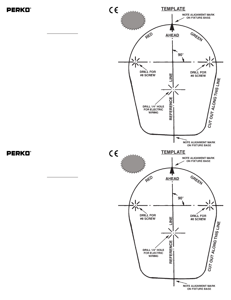
MOUNTING INFORMATION
Read all instructions before proceeding.
1).
For proper light selection, positioning and configuration, refer to A.B.Y.C. Standard A-16*, the 72
COLREGS*, and the U.S. Inland Navigation Rules*. These lights are supplied complete with 12 volt
bulbs (Cat. No. 0071DP0CLR), however 24 volt bulbs (Cat. No. 0072DP1CLR) are available for 24
volt systems. Note: PERKO Series 1161 & 1310 used with 24W bulb 0072DP1CLR is not cert-
ified in accordance with 33 CFR 183.810 as this light is intended for replacement use only on appro-
priate vessels constructed prior to 11/1/03. All previous certifications apply.
2).
These lights are designed to be mounted on a horizontal surface.
3).
Draw a 6 inch long reference line through the center of the selected mounting location and parallel
to the centerline of the boat.
4).
Cut out the mounting template. Place it on to the mounting surface such that the reference line
(drawn above) is directly underneath the reference line marked on the template.
5).
Drill 2 holes through the template to accommodate #8 oval head mounting screws.
Drill a 1/4 inch hole to accommodate the electric wiring.
6).
Attach supply connections to the light, making sure to wire in accordance with both A.B.Y.C.
Standard E-9* and U.S. Coast Guard Safety Standards for Boat Electrical Systems (33 CFR 183)*.
7).
Mount the light in accordance with the template. Note that there are thin reference marks around
the outside of the back of the base that must be aligned with the reference line (drawn in Step #3)
for the final accuracy of the mounting location.
8).
To maintain compliance with regulations, rebulb with PERKO Catalog Numbers
0071DP0CLR (12 Volt 10W) or 0072DP1CLR (24 Volts).
* The above referenced standards can be obtained from:
(1). American Boat & Yacht Council, Inc.
(2) U.S. Coast Guard
613 Third Street, Suite 10
Washington, D.C. 20593
Annapolis, MD 21403
(or your local C.G. office)
12/08
1161INS1
PERKO, INC.
16490 N.W. 13th Avenue
Miami, FL 33169-5707
www.perko.com
USCG APPROVAL
33 CFR 183.810
Visibility: 1nm
Tested By: IMANNA Labs.
Date: 9/25/03
Meets ABYC A-16
12V
Cat. No. 1161 Series Bi-Color Light
Cat. No. 1310 Series Bi-Color Light
The above lights are designed for use on power driven vessels under 12 meters (39.4 ft.) in length, oper-
ating on a nominal 12 volt or 24 volt system. In order to comply with ‘72 COLREGS and the U.S. Inland
Navigation Rules, the following must be adhered to:
MOUNTING INFORMATION
Read all instructions before proceeding.
1).
For proper light selection, positioning and configuration, refer to A.B.Y.C. Standard A-16*, the 72
COLREGS*, and the U.S. Inland Navigation Rules*. These lights are supplied complete with 12 volt
bulbs (Cat. No. 0071DP0CLR), however 24 volt bulbs (Cat. No. 0072DP1CLR) are available for 24
volt systems. Note: PERKO Series 1161 & 1310 used with 24W bulb 0072DP1CLR is not cert-
ified in accordance with 33 CFR 183.810 as this light is intended for replacement use only on appro-
priate vessels constructed prior to 11/1/03. All previous certifications apply.
2).
These lights are designed to be mounted on a horizontal surface.
3).
Draw a 6 inch long reference line through the center of the selected mounting location and parallel
to the centerline of the boat.
4).
Cut out the mounting template. Place it on to the mounting surface such that the reference line
(drawn above) is directly underneath the reference line marked on the template.
5).
Drill 2 holes through the template to accommodate #8 oval head mounting screws.
Drill a 1/4 inch hole to accommodate the electric wiring.
6).
Attach supply connections to the light, making sure to wire in accordance with both A.B.Y.C.
Standard E-9* and U.S. Coast Guard Safety Standards for Boat Electrical Systems (33 CFR 183)*.
7).
Mount the light in accordance with the template. Note that there are thin reference marks around
the outside of the back of the base that must be aligned with the reference line (drawn in Step #3)
for the final accuracy of the mounting location.
8).
To maintain compliance with regulations, rebulb with PERKO Catalog Numbers
0071DP0CLR (12 Volt 10W) or 0072DP1CLR (24 Volts).
* The above referenced standards can be obtained from:
(1). American Boat & Yacht Council, Inc.
(2) U.S. Coast Guard
613 Third Street, Suite 10
Washington, D.C. 20593
Annapolis, MD 21403
(or your local C.G. office)
12/08
1161INS1
PERKO, INC.
16490 N.W. 13th Avenue
Miami, FL 33169-5707
www.perko.com
USCG APPROVAL
33 CFR 183.810
Visibility: 1nm
Tested By: IMANNA Labs.
Date: 9/25/03
Meets ABYC A-16
12V