3 wire diagram – DoorKing 1808 Telephone Access Plus User Manual
Page 59
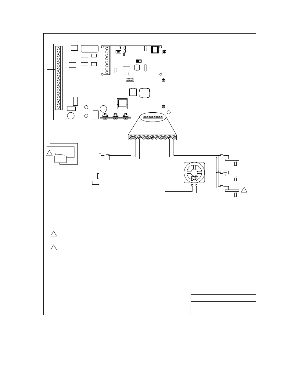
5.3 Wire
Diagram
1
2
3
4
5
6
7
8
9
10
11
12
13
14
15
16
17
18
Mic
Vol
Master
Code
1 2 3 4 5 6 7 8 9 1011
Speaker
Vol
Keypad
1
2
3
4
5
6
7
8
ON
MODEM / TCP ENB
SW 1
Re
d
Wh
it
e
Gr
ee
n
+
-
Gr
ay
O
ran
ge
Pur
p
le
Wh
it
e
DOORKING, INC., INGLEWOOD, CA 90301
Date:
Dwg. No.
Rev.
Title:
1/12
C
M1810AP-001-C
Access Plus
Internal Wire Diagram
M
icro
phon
e PCB
LED PCB
1
2
3
4
5
6
7
8
9
10 11
LED PCB
LED PCB
White
Red
N.C.
N.O.
COM
Micro
Switch
1
2
1
2
Postal micro-switch is used in 1810 Access Plus units only. 1808 Access Plus units
do not have a postal micro-switch.
1810 Access Plus units use three (3) LED lights; 1808 Access Plus units use two (2)
LED lights.
SW2
ON
TERMINATION
OFF
1810-162-J-1-12
Page
59
This manual is related to the following products: