Installation – APC GALAXY 5000 User Manual
Page 40
34001813EN/AE
- Page 40
2. Installation
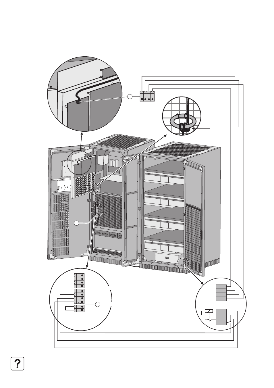
2.18 Control connections for an external battery cabinet
1 - Connect wires 1-2-3-4 on connector XR1 (QF1 position and coil) in the external battery cabinet to connector XMB07 (6)
(SELV) and wires 7-8-9-10 (temperature sensor) to connector XMD3 (22) (SELV).
Note. The wires for the screw-type terminal block are not supplied (max. size 2.5 mm
2
and total length less than 100 m).
8
7
6
5
4
3
2
1
XMD3
XMD3
QF1
-12V
+12V
BC+
BC-
XR1
22
XMB 08 XMB 07 XMB 06
6
5
12V
+
12V
BC
+
BC
Circuit breaker 2
Common
Open-close contact
QF1 command
Circuit breaker 1
Pass through
three times
See also other documents in the category APC Tools:
- ROCK MOUNT 2200 (2 pages)
- 990-1387A (15 pages)
- 1500 (21 pages)
- VS 100 (65 pages)
- SMART-UPS 230VAC (1 page)
- Smart-UPS RT SURTA48XLBP (12 pages)
- SMARTUPS Smart-UPS 3000 (60 pages)
- BK400EI (40 pages)
- UPS control system (233 pages)
- 60-80kW (80 pages)
- Silcon DP300E Series (38 pages)
- 990-2902C (1 page)
- SILCON 990-4053 (76 pages)
- Step-Down Transformer AP9626 (10 pages)
- SMART-UPS 990-1841A (1 page)
- 600 (44 pages)
- 900XL (44 pages)
- 750VA (1 page)
- SMARTUPS Smart-UPS 2200 (2 pages)
- SMART-UPS 2200 (2 pages)
- SUA3000 (22 pages)
- 2200VA (25 pages)
- UPS (18 pages)
- SMART-UPS 990-7016B (2 pages)
- 208 Vac (24 pages)
- SU700RM2U (2 pages)
- Call-UPSII AP9208 (52 pages)
- ES 500 (2 pages)
- RS 500 (2 pages)
- 5000T (33 pages)
- Smart-UPS URTA48XLBPJ (12 pages)
- 420 (66 pages)
- SMART-UPS SUA2200 (22 pages)
- SYMMETRA SYCFXR9 (36 pages)
- SILCON 60-80KW 208/480V UPS (34 pages)
- MODULAR RACK-MOUNT POWER 990-3051C-001 (4 pages)
- SGI 15000 RAID (152 pages)
- Switched Rack Power Distribution Unit (PDU) (93 pages)
- SMART-UPS XL SUA48XLBP (9 pages)
- Smart-UPS VT (44 pages)
- 6000 VA (13 pages)
- NETBOTZ NBRK0200 (36 pages)
- BC300 Series (38 pages)
- BR800I (2 pages)