Installation – APC GALAXY 5000 User Manual
Page 29
34001813EN/AE
- Page 29
2. Installation
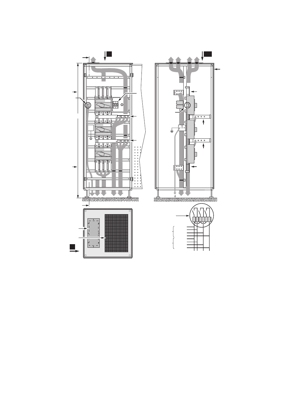
2.10 Connection of the 360 kVA external bypass cabinet
Key
AA: section AA of cabinet
B: front view of cabinet
C: front
D: connection of Bypass AC source to the UPSs
E: connection of auxiliary wires for position of Q4S, Q3BP and Q5N switches
F: connection of UPS load outputs
G: connection of Bypass AC source
H: connection of the load
I : ventilation grate for air exit from cabinet
J: cable running through top, 460 x 197 mm opening and gland plate
K: protection fuses for RC voltage surge suppressor on the Bypass AC line (must be replaced when LED is ON)
L: top view of cabinet
C
D
G
H
F
E
A
1900
A
L1 L2 L3
N
L1 L2 L3
N
L1 L2 L3
L1 L2 L3
N
H
G
E
K
I
J
B
AA
L
UPS 1
XMS04 /
XMS05
UPS 2
UPS 3
UPS 4
E
Q4S
Q3BP
Q4S
Q3BP
Q5N
N
D
F
Q5N
XMS04 /
XMS05
1 2 3 4 5 6
See also other documents in the category APC Tools:
- ROCK MOUNT 2200 (2 pages)
- 990-1387A (15 pages)
- 1500 (21 pages)
- VS 100 (65 pages)
- SMART-UPS 230VAC (1 page)
- Smart-UPS RT SURTA48XLBP (12 pages)
- SMARTUPS Smart-UPS 3000 (60 pages)
- BK400EI (40 pages)
- UPS control system (233 pages)
- 60-80kW (80 pages)
- Silcon DP300E Series (38 pages)
- 990-2902C (1 page)
- SILCON 990-4053 (76 pages)
- Step-Down Transformer AP9626 (10 pages)
- SMART-UPS 990-1841A (1 page)
- 600 (44 pages)
- 900XL (44 pages)
- 750VA (1 page)
- SMARTUPS Smart-UPS 2200 (2 pages)
- SMART-UPS 2200 (2 pages)
- SUA3000 (22 pages)
- 2200VA (25 pages)
- UPS (18 pages)
- SMART-UPS 990-7016B (2 pages)
- 208 Vac (24 pages)
- SU700RM2U (2 pages)
- Call-UPSII AP9208 (52 pages)
- ES 500 (2 pages)
- RS 500 (2 pages)
- 5000T (33 pages)
- Smart-UPS URTA48XLBPJ (12 pages)
- 420 (66 pages)
- SMART-UPS SUA2200 (22 pages)
- SYMMETRA SYCFXR9 (36 pages)
- SILCON 60-80KW 208/480V UPS (34 pages)
- MODULAR RACK-MOUNT POWER 990-3051C-001 (4 pages)
- SGI 15000 RAID (152 pages)
- Switched Rack Power Distribution Unit (PDU) (93 pages)
- SMART-UPS XL SUA48XLBP (9 pages)
- Smart-UPS VT (44 pages)
- 6000 VA (13 pages)
- NETBOTZ NBRK0200 (36 pages)
- BC300 Series (38 pages)
- BR800I (2 pages)