Installation – APC GALAXY 5000 User Manual
Page 16
34001813EN/AE
- Page 16
2. Installation
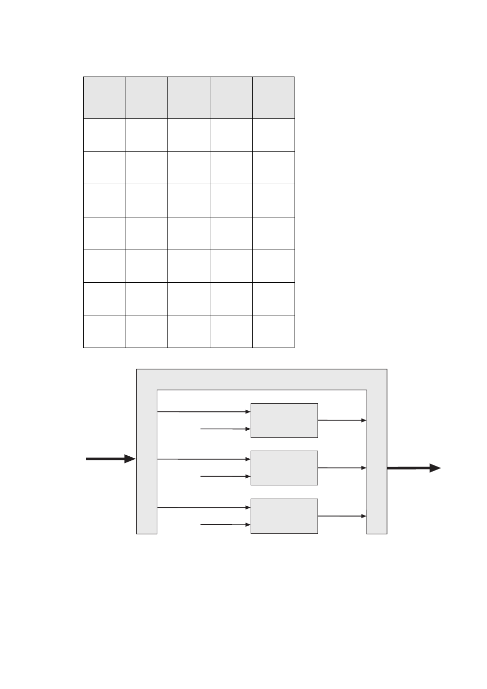
Required cable sizes for parallel UPS installations with an external bypass
Rated
power of
each UPS
unit
Number of
parallel
UPS units
Total rated
power of
the UPS
Bypass AC
input or
load line
current
Cable
size
(1)
in mm
2
The table opposite is an example for an
installation with up to four UPS units.
◗
For installations with redundant units, take
into account only the number of units required
to supply the loads (e.g. in a three-unit
installation where one unit is redundant, only
two units count in determining the input and
load currents).
◗
This table is valid for 400 V input and load
phase-to-phase voltages, at rated load with a
power factor of 0.8. For voltages of 380 or
415 V, multiply the current values by 1.05 or
0.96 respectively and, if necessary, modify
the cable sizes accordingly.
◗
The cable sizes in this table concern the bold
sections in the diagram below.
(1) Cable sizes are determined for U1000
R02V type copper conductors (for aluminium
conductors, increase the size by 30%). Size
calculations also take into account a voltage
of 400 V and grouping of four cables.
20 kVA
2
3
4
40 kVA
60 kVA
80 kVA
58 A
87 A
116 A
16
35
50
30 kVA
2
3
4
60 kVA
90 kVA
120 kVA
80 A
129 A
172 A
25
50
70
40 kVA
2
3
4
80 kVA
120 kVA
160 kVA
116 A
174 A
232 A
35
70
120
60 kVA
2
3
4
120 kVA
180 kVA
240 kVA
174 A
261 A
348 A
70
150
185
80 kVA
2
3
4
160 kVA
240 kVA
320 kVA
232 A
348 A
464 A
120
185
2 x 120
100 kVA
2
3
4
200 kVA
300 kVA
400 kVA
288 A
432 A
576 A
150
2 x 95
2 x 150
120 kVA
2
3
4
240 kVA
360 kVA
480 kVA
348 A
522 A
696 A
185
2 x 150
2 x 185
Bypass AC
Normal AC
Bypass AC
GALAXY 5000
1
Normal AC
Bypass AC
GALAXY 5000
2
Normal AC
Bypass AC
GALAXY 5000
3
Load
External bypass