System design considerations, Design for calibration – Liquid Controls MS Meters User Manual
Page 8
8
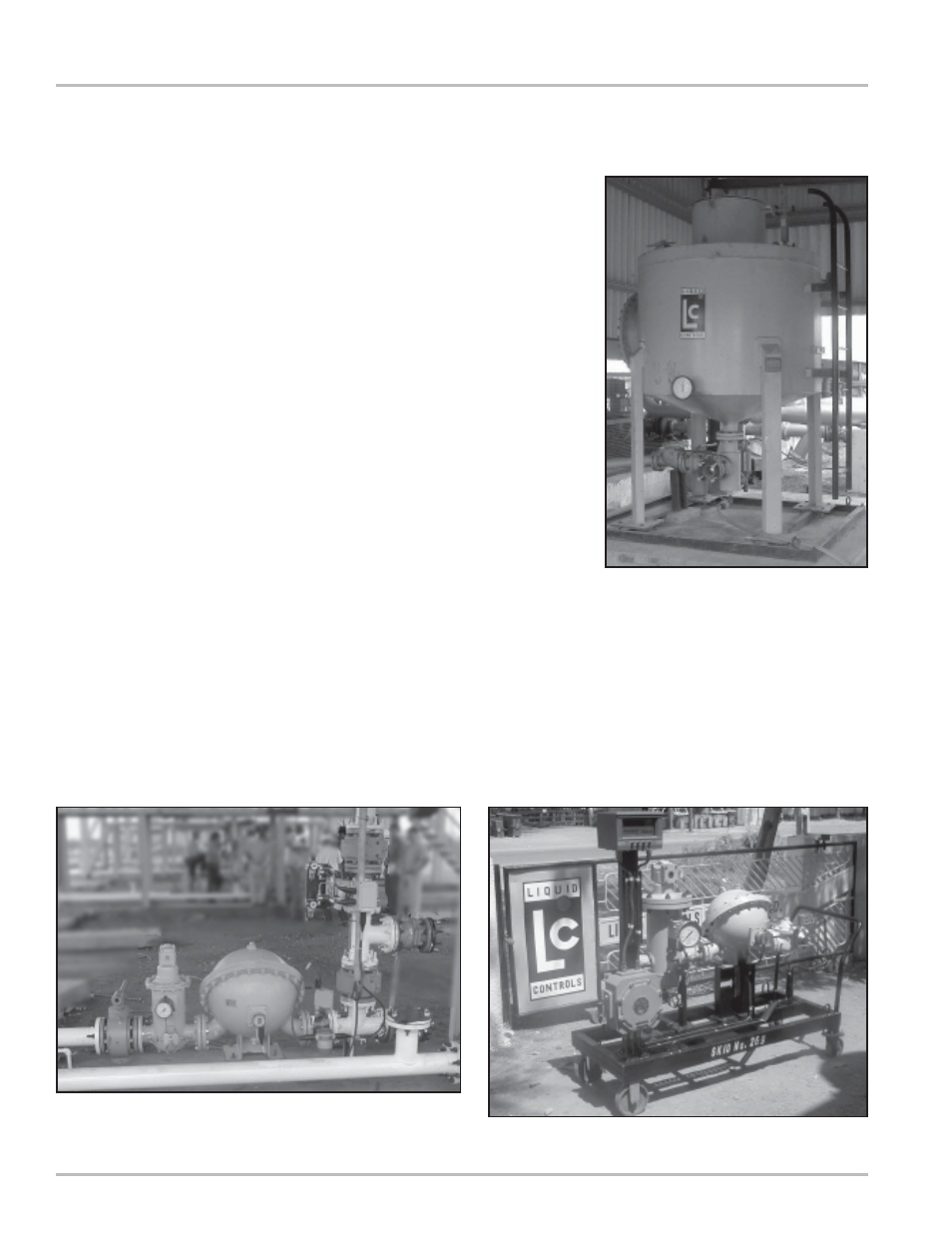
Mobile Master Proving Trolley
Proper Meter Installation
Volumetric Prover
System Design Considerations
Design For Calibration
Field calibration of meters is essential. Calibration
conducted during meter production is to confirm the meter
is capable of attaining the required accuracy/linearity and
repeatability.
Typically, the meter characteristics are:
Mechanical Registration
•
Repeatability: Capable of .02% or better at any flow
rate over entire range
•
Linearity: ± .125% over a 5:1 range
•
Linearity: ± .22% over a 10:1 range
•
Linearity: ± .5% over a 40:1 range
Electronic Registration
•
Repeatability: Capable of .02% or better at any flow
rate over entire range
•
Linearity: ± .1% over a 5:1 range
•
Linearity: ± .1% over a 10:1 range
•
Linearity: ± .15% over a 40:1 range
The meters are normally tested against a master meter
that has been proven against a Weights & Measures
certified, volumetric prover.
The pictures below show a properly configured meter
installation and mobile master prover. The prover
connections are at the right. The two valves to the left of
the meter are for connecting the volumetric prover or
master meter to be used for calibration. The valve
mounted in the vertical line between the two horizontally
mounted valves is a double-block, bleed valve used to
ensure there is no leakage through the valve during
calibration.