Reversing the meter registration – Liquid Controls MS Meters User Manual
Page 13
13
Reversing the Meter Registration
The direction of flow is specified by the customer when
the meter is ordered. The standard direction of flow is
from left to right when facing the front of the meter. A red,
pressure sensitive label indicating the inlet is affixed to
the meter at the time of shipment.
If the meter is equipped with a strainer and/or valve, the
strainer and/or valve MUST be moved when reversing
the direction of flow through the meter. The strainer
should always be located on the inlet side of the meter.
When the meter is equipped with a valve, it is moved to
the outlet side of the meter. Some repositioning of the
valve components may be required. See the Valve
Manual in the Owner’s Information Packet.
When the meter is first installed, check the register. If the
register counts DOWN (numbers decrease) the direction
of registration must be reversed by either reversing the
position of the adjuster drive gear or by reprogramming
the direction of flow using the Lap Pad (for LectroCount
electronic registration). Consult the LectroCount
Operation Manual provided in the Owner’s Information
Packet.
Reversing the drive to the register is accomplished by
reversing the position of the adjuster drive gear relative
to the pinion gear of the packing gland.
1.
See Meter Maintenance on Page 15 and “Servicing the Drive
Components” on Page 17, for instructions on removing the dust cover.
2.
Remove the retaining spring screw(s) (1) with a standard screwdriver.
3.
Remove the retaining spring (2).
4.
Remove the drive shaft (3) mounted with the adjuster driver gear
assembly (4, Retaining Ring) (5, Adjuster Drive Gear).
5.
Remove the retaining ring (4) with a screwdriver or pliers.
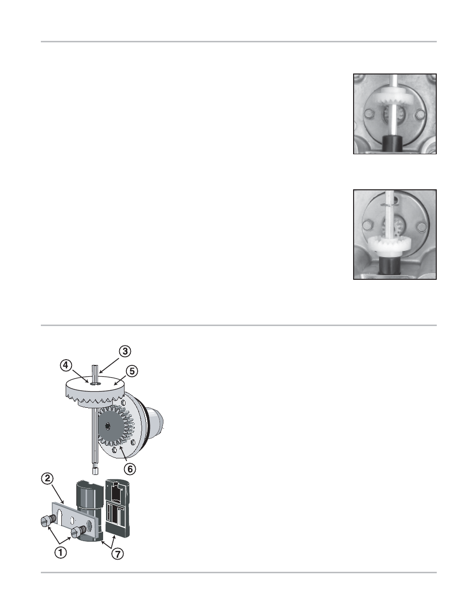
6.
Remove the adjuster driver gear (5) and turn it 180° so that it is upside
down from the original installed position. The bushing (7) supports the
adjuster drive gear in the lower position. The retaining ring (4) supports
the adjuster drive gear in the upper position.
7.
Reassemble the parts in reverse order. Make sure that the adjuster
driver gear meshes with the packing gland’s pinion gear (6) without
being too tight. Make sure there is a little play in the gear teeth. The
retaining ring (4) should be placed in the grove provided on the drive
shaft (3) regardless of the adjuster drive gear position. The packing
gland pinion gear to adjuster drive gear ratio is either 1:1 or 2:1. In the
2:1 ration, the pinion of the packing gland is smaller in diameter.
Adjuster drive
gear engaged
from the top.
Adjuster drive
gear engaged
from the bottom.