Disassembling the meter, Removing the rotor gears – Liquid Controls MS Meters User Manual
Page 22
22
Disassembling the Meter
3.
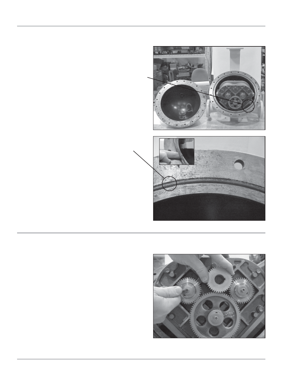
When all the screws and bolts have been removed,
remove the weldment cover. This exposes the inside
of the weldment assembly and provides access to
the meter assembly. The meter assembly is held in
place by 4 bolts on the inlet side of the meter. This
can be either side of the meter depending on the
direction of flow.
Access to these four bolts is gained by removing the
front bearing plate of the meter housing.
4.
Remove the O-Ring from the weldment assembly.
Undamaged O-Rings may be reused.
5.
Hold a spare displacement rotor gear between the
right displacement rotor gear and the blocking rotor
gear to keep them from turning. If a spare gear is
not available, use a shop rag between the gear teeth.
Use the rotor gear allen key to loosen the rotor gear
screw by turning it counter-clockwise. Do not remove
the screw completely.
NOTE: Do not use a metallic tool for locking the gears
as this will likely result in damage to the gear teeth.
Removing the Rotor Gears
- Gear Plate Selection Guide (24 pages)
- MA4 Meter (32 pages)
- M-MA Meters (28 pages)
- HMS3700 & HMS3770 Insertion Sensors LC Mag Insertion (8 pages)
- HMS501, HMS600, HMS1000, HMS2400, HMS2500, and HMS5000 LC Mag IOM (8 pages)
- CIM100 (16 pages)
- Rate of Flow (4 pages)
- HML4-F1 - LCMag (40 pages)
- LCRII Install E3650-E3651 Series (40 pages)
- LCR-II Setup & Operation (60 pages)
- LCRII Menu Map (2 pages)
- LCR-II - Quick Reference (2 pages)
- LCR Install (24 pages)
- LCR Setup & Operation (60 pages)
- LCR 600 Install (36 pages)
- LCR600 Wiring Schematic (1 page)
- LCR 600 Setup & Op (68 pages)
- LCR 600 - Quick Reference (2 pages)
- FlightConnect 600 (52 pages)
- FlightConnect 600 QR (2 pages)
- LCR-II Installation E3655-E3656 (36 pages)
- LCRII E3651-E3656 Wiring Schematic (1 page)
- DMS Installation (20 pages)
- DMS Setup (84 pages)
- DMS Delivery (52 pages)
- DMS i1000 Quick Reference - DMS Delivery (2 pages)
- DMS Office (52 pages)
- DMS i1000 EZConnect Operators (36 pages)
- DMS i1000 Quick Reference - EZConnect (2 pages)
- EZConnect Office (44 pages)
- FlightConnect Office (36 pages)
- FlightConnect Setup Guide (8 pages)
- DB Manager (20 pages)
- POD (16 pages)
- Dual Meter Multiplexer (8 pages)
- Differential Pressure Transducer (12 pages)
- XL LED Display E1615_E1616_E1617_E1618 (20 pages)
- SCAMP (20 pages)
- WinHost Operation (44 pages)
- SP714-S2i (12 pages)
- HML110 IOM (31 pages)
- HML210 IOM - LCMag (44 pages)
- Sponsler T675 - Cryogenic System Register (54 pages)
- Sponsler IT400 Electronic Register (40 pages)