System design considerations – Liquid Controls MS Meters User Manual
Page 7
7
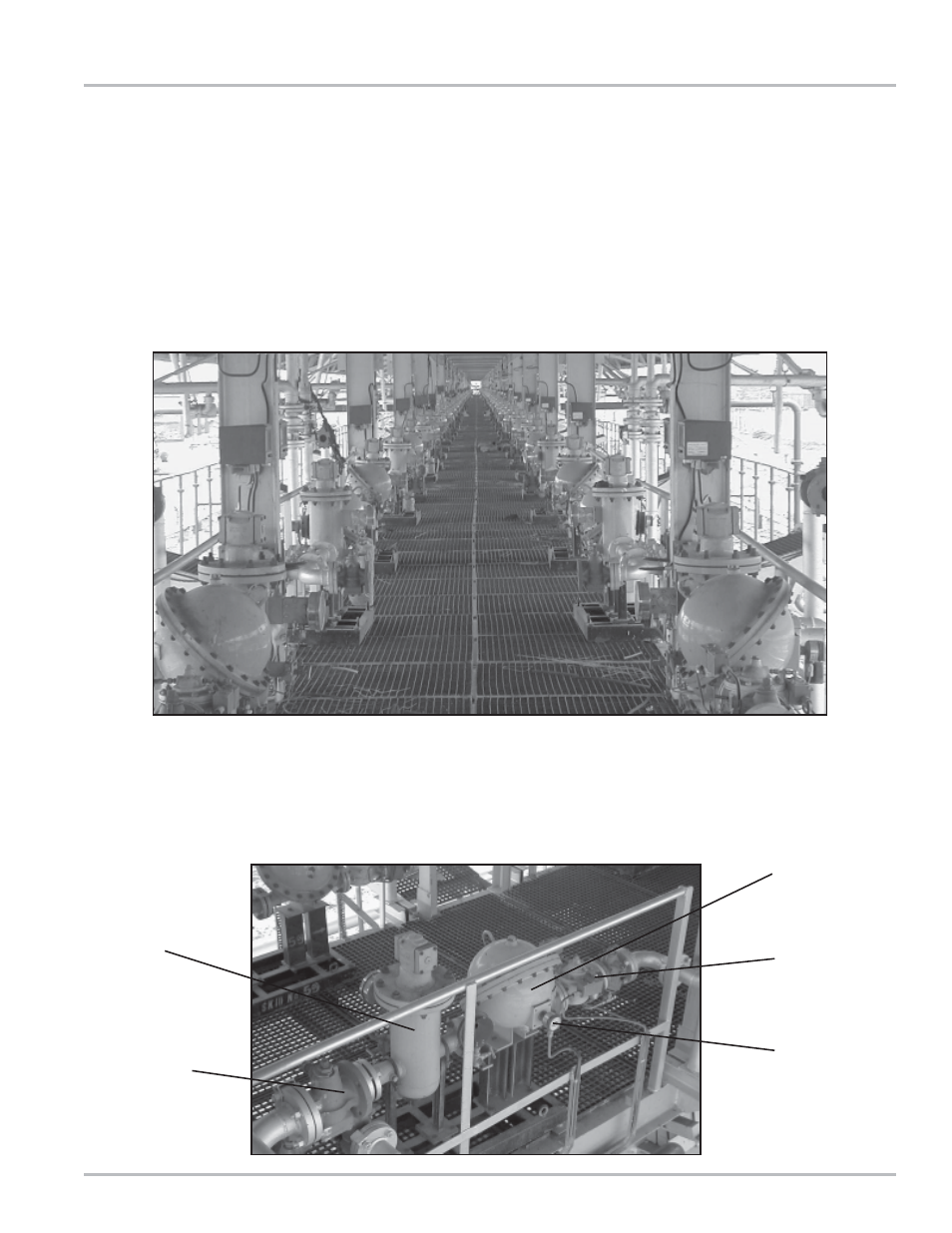
Strainer/Air
Eliminator
Supply Side
Isolation Valve
MS Series Meter
Outlet Side
Isolation Valve
Pulse Output
Device (POD)
System Design Considerations
Flowmeters must be installed properly if accuracy and
repeatability of measurements are to be sustained over
long periods of time. The system in which the meters
are to be used must have provisions for controlling flow,
transitional, and no flow conditions. Pressure, both
hydrostatic and hydrodynamic, must be an integral part
of the variables controlled in the flowing system. Systems
in which meters are to be installed must be designed to
eliminate transient pressure conditions, eliminate
thermally induced pressure increases, and to exclude
air or vapor.
The next photograph shows a typical gantry position.
From left to right, there is a supply line attached to an
isolation valve, a second isolation valve and piping
leading vertically to the loading arm. The meter is
equipped with a dual channel, quadrature pulse
The complete system must be kept full of product at all
times. The photograph below is a typical fuel delivery
gantry designed for loading rail tank wagons. This
particular gantry has provisions for loading 152 rail tank
wagons at one time. Four different fuels are supplied to
the gantry through 16 inch pipe lines which are
approximately ½ mile long. The pumps are centrifugal
type and are located between 100 and 300 yards from
the storage tanks.
transmitter connected directly to a batch controller. The
batch controller provides preset batch capability, flow rate
control, and slow flow start and stop. There is one batch
controller for each metering position.