Laurel Electronics LAUREATE SERIES COUNTER_TIMER User Manual
Page 48
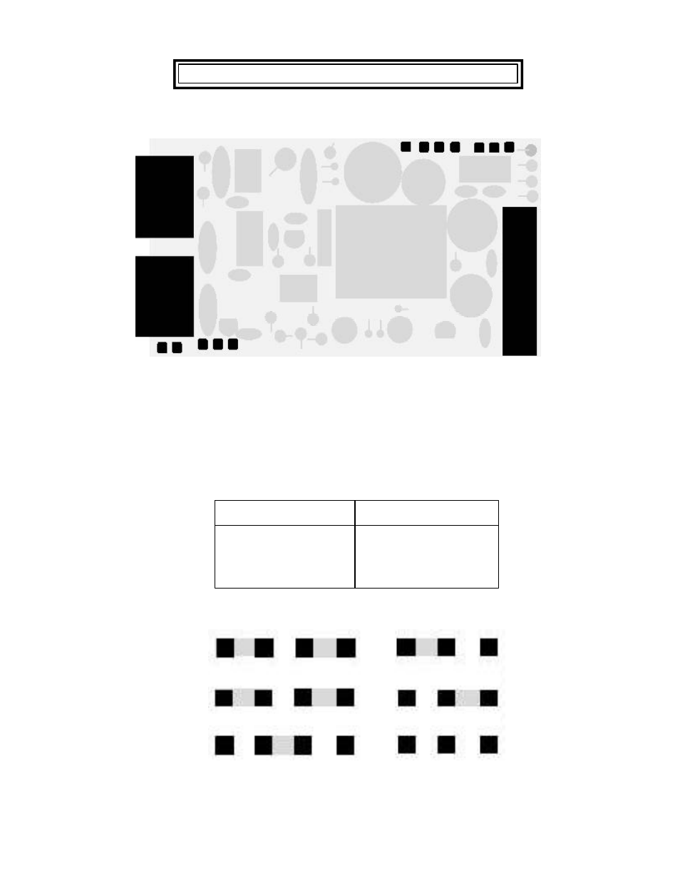
18.
5, 10 AND 24 VDC EXCITATION OUTPUTS
a
Jumper ' a ' - Front panel menu lockout (see Section 9.1)
Jumper ' h ' - External Input B at output connector P1 - 4
Jumper ' g ' - +5V at output connector P1 - 4
c
b
d
e f
h g
Figure 18. 1 - Power Supply
-46-
18. 1 SELECTION OF 5, 10 OR 24VDC OUTPUT
Voltage Output
Jumper Locations
5 Vdc
b, d and e
10 Vdc
b, d and f
24 Vdc
c
e
5 Vdc
10 Vdc
24 Vdc
b
d
b
f
d
c
Note: The excitation power supply is floating with respect to meter ground. When power-
ing transducers that have a common signal low and power supply return lead,
jumper minus excitation to signal ground.
See also other documents in the category Laurel Electronics Hardware:
- QLS Quad Output 4-20 mA Current Loop - Datasheet (3 pages)
- QLS Quad Output 4-20 mA Current Loop - Manual (8 pages)
- LTS6 - Datasheet (3 pages)
- LTS6 - Manual (24 pages)
- LT: 4-20 mA & Serial Data Output Transmitter for Duty Cycle Input (4 pages)
- LT SERIES TRANSMITTERS PULSE INPUTS (40 pages)
- LT: 4-20 mA & Serial Data Output Transmitter for Position or Rate from Quadrature Encoders (4 pages)
- LT: 4-20 mA & Serial Data Output Transmitter for Average Time of Periodic Events (4 pages)
- LT: 4-20 mA & Serial Data Output Transmitter for Time of Single or Accumulated Events (4 pages)
- LT: 4-20 mA & Serial Data Output Transmitter for AC Phase Angle & Power Factor (4 pages)
- LT: 4-20 mA & Serial Data Output Transmitter for Ratio (4 pages)
- LT: 4-20 mA & Serial Data Transmitter-Totalizer for 0-1 mA, 4-20 mA or 0-10V Process Signals (4 pages)
- LT: 4-20 mA & Serial Data Output Transmitter for Dual Channel Pulse Totalizer Input (4 pages)
- LT: Ethernet & 4-20 mA Output Transmitter for Frequency, Rate or Period Input (4 pages)
- LT SERIES TRANSMITTERS ANALOG INPUT (40 pages)
- LT: 4-20 mA Current Loop Transmitter for Resistance Input in Ohms (4 pages)
- LT: 4-20 mA & Serial Data Output Transmitter for Pt100, Cu10 and Ni120 RTD Input (4 pages)
- LT: 4-20 mA & Serial Data Output Transmitter for Thermocouple Types J, K, T, E, N, R, S (4 pages)
- LT: 4-20 mA & Serial Data Output Transmitter for Load Cell & Microvolt Signals (4 pages)
- LTE SERIES TRANSMITTERS ANALOG INPUT (40 pages)
- LTE: Ethernet & 4-20 mA Output Transmitter for Strain Gauge & Potentiometer Input (4 pages)
- LT: 4-20 mA & Serial Data Output Transmitter for Process Signals (4 pages)
- LT: 4-20 mA & Serial Data Output Transmitter for AC RMS Voltage or Current Input (4 pages)
- LT: 4-20 mA & Serial Data Output Transmitter for DC Voltage or Current Signals (4 pages)
- LTE SERIES TRANSMITTERS PULSE INPUT (40 pages)
- LTE: Ethernet & 4-20 mA Output Transmitter for Duty Cycle Input (4 pages)
- LTE: Ethernet & 4-20 mA Output Transmitter for Position or Rate from Quadrature Encoders (4 pages)
- LTE: Ethernet & 4-20 mA Output Transmitter for Average Time of Periodic Events (5 pages)
- LTE: Ethernet & 4-20 mA Output Transmitter for Time of Single or Accumulated Events (4 pages)
- LTE: Ethernet & 4-20 mA Output Transmitter for AC Phase Angle & Power Factor (4 pages)
- LTE: Ethernet & 4-20 mA Output Transmitter for Ratio (5 pages)
- LTE: Ethernet & 4-20 mA Output Transmitter & Totalizer for 0-1 mA, 4-20 mA or 0-10V Signals (4 pages)
- LTE: Ethernet & 4-20 mA Output Transmitter for Dual Channel Pulse Totalizer Input (4 pages)
- LTE: Ethernet & 4-20 mA Output Transmitter for Frequency, Rate or Period Input (4 pages)
- LTE: Ethernet & 4-20 mA Output Transmitter for Resistance in Ohms (4 pages)
- LTE: Ethernet & 4-20 mA Output RTD Transmitter for Pt100, Cu10 and Ni120 RTD Input (4 pages)
- LTE: Ethernet & 4-20 mA Output Transmitter for Thermocouple Types J, K, T, E, N, R, S (4 pages)
- LTE: Ethernet & 4-20 mA Transmitter for Load Cell & Microvolt Signals (4 pages)
- LTE: Ethernet & 4-20 mA Output Transmitter for Process Signals (4 pages)
- LTE: Ethernet & 4-20 mA Output Transmitter for AC RMS Voltage or Current (4 pages)
- LTE: Ethernet & 4-20 mA Output Transmitter for DC Voltage or Current (4 pages)
- LTSE6 - Manual (25 pages)
- LTSE6 - Datasheet (3 pages)
- MAGNA Series Large Digit Displays (4 pages)
- M-35 Microminature Process Meter (2 pages)