Laurel Electronics LAUREATE SERIES COUNTER_TIMER User Manual
Page 25
-23-
11.
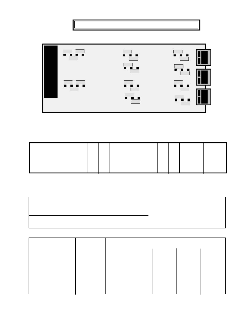
DUAL CHANNEL SIGNAL CONDITIONER
11.1
SETTING JUMPERS FOR INPUT SIGNAL LEVELS
A3 A2
Low
High
B3 B2 Threshold Threshold
b
a
-60mV
-30mV
b
b
-600mv -350mV
b
-
-2.1V
-1.25V
A3 A2
Low
High
B3 B2 Threshold Threshold
a
a
+30mV
+60mV
a
b
+350mV +600mv
a
-
+1.25V
+2.1V
A2
Low
High
B2 Threshold Threshold
a
-12mV
+12mV
b
-150mV
+150mV
-
-1.15V
+1.15V
Jumper Definition and Debounce Circuit
Pullup or pulldown resistors are used with open collector devices and dry contact closures to provide
input signal bias and should not be connected for other inputs. The debounce circuit keeps the meter
from counting extra pulses due to contact bounce.
Minimum High and Low Input Signal Levels
The jumper settings for Channel A (A2 & A3) and Channel B (B2 & B3) are selected depending on the
input amplitude. The input signal voltage must exceed the high and low threshold per the following table
or the meter will not operate properly. The larger the difference between the high and low thresholds,
the more immune the meter is to input signal noise.
A0 & B0
-
1MHz Input max
b
30KHz Input max
a
250Hz max
A1 & B1
a
2Kohm input pullup +5V
A1 & B1
b
2Kohm input pulldown -5V
A4 & B4
Time Constant
(Debounce)
b
None
a, c
3 mSec
c
50 mSec
11.2
COMMON JUMPER SETTINGS
Input type
Channel A and B Jumpers
A0 & B0
A1 & B1 A2 & B2
A3 & B3
A4 & B4
-
b
b
a or b
b
b
b
b
b
a, c
a, c
b
-
a
b
a
-
-
-
-
-
-
-
a
a
a
b
a
-
-
Vmax
250
NA
NA
NA
250
250
Logic Levels
Open Collector
Npn Transistor
Pnp Transistor
Contact closures
Line Frequency
Turbine Flow
Note: All Channel A and Channel B settings may be different based on input signal type.
B1
a
a
a
a
a
b
b
b
b
b
B3
B2
B0
B4
A4
A3
A2
A1
A0
a
b
c
b
b
a
b
a
a
Channel B
Channel A
a
b
c