Parallel bcd output – Laurel Electronics LAUREATE SERIES COUNTER_TIMER User Manual
Page 47
17.
PARALLEL BCD OUTPUT
17. 1 OPERATING MODE MENU SELECTION
The following menu items are accessible only with a BCD option installed and appropriate
lockouts enabled. See Section 10 for further information.
17. 2 BCD OUTPUT LEVELS
The BCD option provides isolated, buffered, stored, 3-state parallel outputs that are selectable
for either 0 to 5V logic levels (LSTTL, CMOS compatible) or 0 to 15Vdc. Selection jumpers are
located on the BCD board. BCD outputs are positive true. Polarity bit is positive true for +sign.
LOGIC LEVEL
JUMPER REQUIRED
0 to 5Vdc
b
0 to 15Vdc
a
17. 3 BCD CONTROL SIGNALS
Enable
Logical 0 - All outputs go to the high impedance state
Logical 1 - BCD information is available at outputs.
BCD Hold
Logical 0 - BCD from last update prior to BCD Hold going low is stored
Logical 1- BCD information updates at selected rate.
Data Ready Logical 0 - BCD outputs are valid
Logical 1 - BCD outputs are not valid
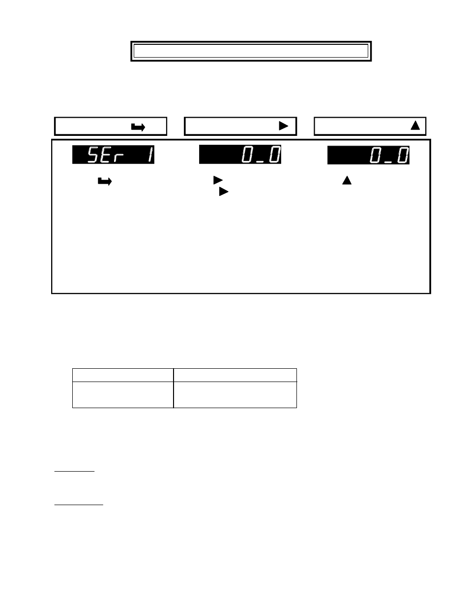
VALUE SELECT KEY
Press the
key until SEr
1 (Serial interface setup 1) is
displayed.
Press to display status.
Press again to select
digit. Selected digit will flash.
Digit 3: Output filtering
Digit 5: Output update rate
Press to select value for
flashing digit
3: "0"-Send unfiltered signal
"1"-Send filtered signal
5: "0"-Line frequency
"1" to "9"
- Batch display rate (3.5/
sec) to Batch display rate
/ 256 (1 every 15 min.)
1 2 3 4 5
1 2 3 4 5
MENU KEY
DIGIT SELECT KEY
-45-