Pad mounting (sw470), Figure 2, Figure 1 figure 2 – Controlled Products Systems Group SW4705011G3 User Manual
Page 9
9
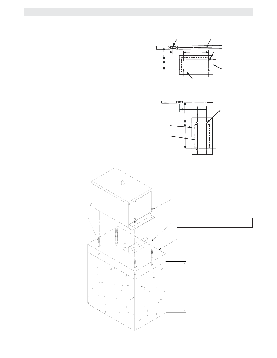
1/2" RED HEAD BOLTS
0R ANCHORS (4 REQUIRED)
2" TO 4"
ABOVE GRADE
DEPTH REQUIRED
BY LOCAL CODES OR
BELOW FROST LINE
POWER AND CONTROL WIRING
SHOULD BE RUN IN SEPERATE CONDUIT
CONCRETE
PAD
USING SUITABLE
HARDWARE SECURE
OPERATOR TO L-BOLTS
PAD MOUNTING (SW470)
NOTE: For the following instructions refer to figures 1
& 2.
1. Layout the concrete pad as detailed in figure 1.
IMPORTANT NOTE: The relative location of the oper-
ator to the fence and the gate is critical. Be sure that
the measurements for operator mounting are taken
from the centerline of the fence and of the gate hinge.
2. Locate electrical conduit, as required, prior to pour-
ing concrete.
3. Pour concrete pad.
4. Bolt the (2) pad mount brackets to the bottom of
the operator with the hardware provided.
5. Secure the operator to the pad. It is very impor-
tant that the operator be level and square to the gate.
GATE
CONCRETE PAD
18" X 34" MIN.
PROFILE OF
OPERATOR
SW470
PERPENDICULAR
CENTERLINE
1/2" REDHEAD
(4 REQ'D)
16"
8"
18-3/4"
22-1/2"
HINGE PIN
FENCE
9-3/4"
22-1/2"
24"
C
L
8"
1/2" REDHEAD
(4 REQ'D.)
CONCRETE PAD
18" X 34" MIN.
OPERATOR
PARALLEL MOUNT
PERPENDICULAR MOUNT
FIGURE 1
FIGURE 2