Controller programming and features, Motor learn button, Force control – Controlled Products Systems Group SW4705011G3 User Manual
Page 21
21
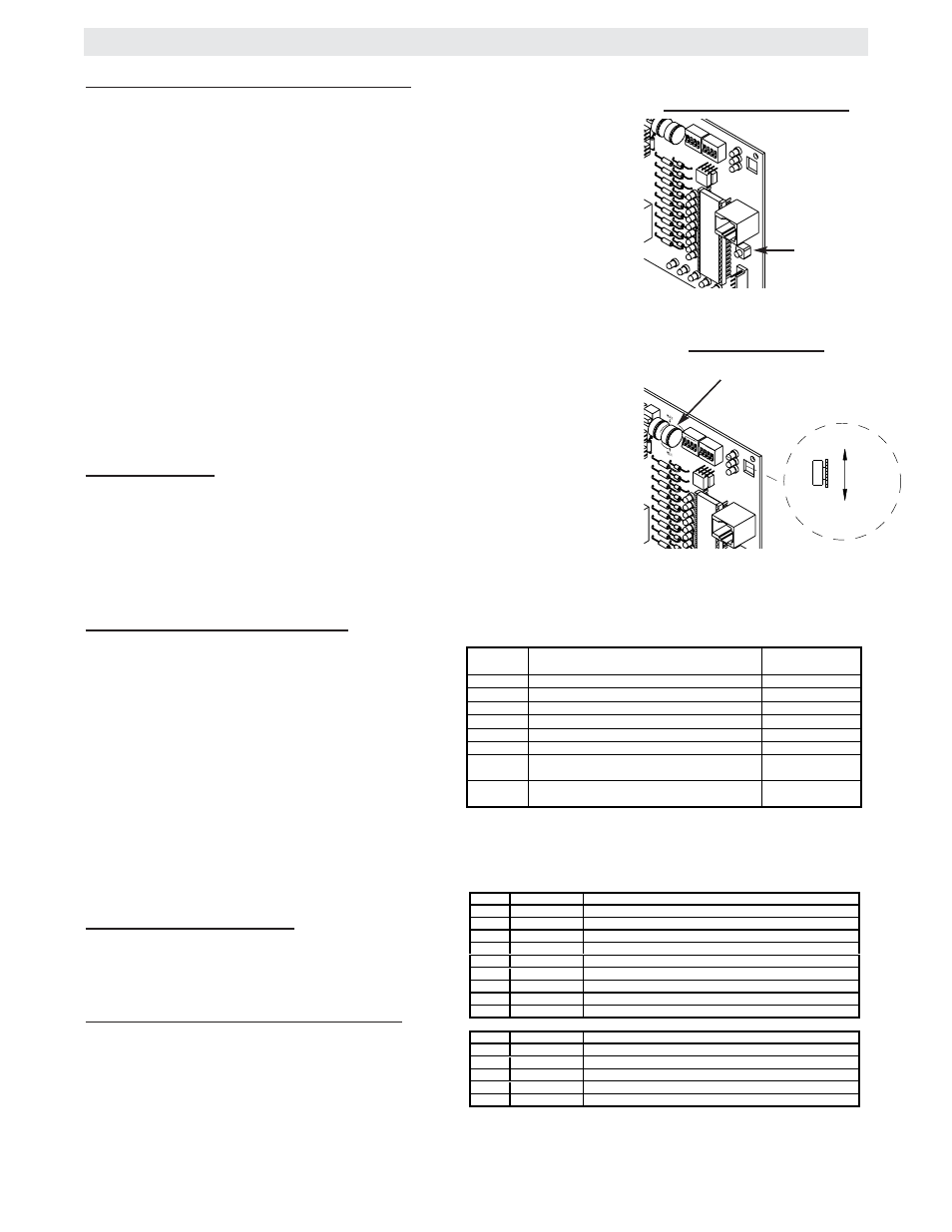
MOTOR LEARN FUNCTION (FORCE PROFILE)
This function is preprogrammed at factory. If either board or motor is replaced, the
controller will need to be programmed to “LEARN” the specific motor RPM profile
only of your operator. Switch “S3” is provided for this. This is important for accu-
rate force control. Failure to do so may result in improper and unsafe operation.
To learn the motor:
NOTE: Motor Learn must be performed in stand along mode.
1. Detach the unit from the gate, the motor needs to be learned without a load.
2. Press the motor learn button. The yellow LED should start to flash rapidly.
3. Install a jumper on either the hard open or the hard close input terminals. The
motor will run for a few seconds and then stop. If the LED goes out the motor is
learned. If the unit activates a limit before completing the learn or some other error
occurs the LED will go back to on continuously. If this happens try learning while
running in the opposite direction.
NOTE: It is important that the jumper is in constant contact while the gate is
moving in learn mode.
4. Reconnect the unit to the gate, reset the limits and adjust the force control.
FORCE CONTROL
Set the force control pot such that the unit will complete a full cycle of gate travel
but can be reversed off an obstruction without applying an unreasonable amount of
force. On most operators this will be around the middle of the range.
CONTROLLER PROGRAMMING AND FEATURES
DIAGNOSTICS (LEDS AND CODES)
There are three diagnostic LEDs. Two red LEDs
(OL, CL) are indicators for the open and close limits.
The LEDs are illuminated when the limit switch con-
tacts are closed.
The third amber LED (DIA) is used to blink out diag-
nostic codes. The number is the count of the num-
ber of times the LED is on in an 8 second period.
The LED is on for approximately 1/2 second and
repeats every second until the number is reached.
There will be a pause following each pulse cycle (1-
6 pulses) to differentiate between the different diag-
nostic codes.
TROUBLESHOOTING LED’S
There are 9 troubleshooting LEDs (D11, D13, D15,
D17, D19, D21, D24, D29, D31).
RELAY DRIVE TROUBLESHOOTING LED’S
There are 5 troubleshooting LEDs (D2, D3, D4, D5,
D6) on relay drives K1 through K5. These LEDs will
be illuminated when the microcontroller relay drive
is activated.
LED CODE
FLASHED
DIAGNOSTIC
MEANING
CLEARED BY
OFF
Normal operation.
N/A
1
Single entrapment sense.
Control Input
2
Double entrapment sense.
Hard Input*
3
Failed or no hall effect sensor.
Removal of problem.
4
Exceed maximum motor run time.
Hard Input*
5
Limit fault.
Control Input*
6
Loss of communications between master and
second during run mode.
Removal of problem.
ON
NO FLASH
Motor not learned.
Completion of motor
Learn Routine
LED NAME
LED
DESCRIPTION
RADIO
On when radio switch activated.
SHADOW
On when shadow loop is activated.
HARD CLOSE
On when hard close switch is activated.
STOP
On when stop switch is not activated.
SOFT OPEN
On when soft open switch is activated.
HARD OPEN
On when hard open switch is activated.
INT. LOOP
On when interrupt/safety loop activated.
OBS. OPEN
On when edge is activated or when photo eye beam is broken.
OBS. CLOSE
D11
D13
D15
D17
D19
D21
D24
D29
D31
On when edge is activated or when photo eye beam is broken.
LED NAME
LED
DESCRIPTION
CONT A
On when CONTACTOR A activated.
CONT B
On when CONTACTOR B activated.
SAM
On when Sam Relay is activated.
LOCK
On when Mag Lock Relay is activated.
ALARM
D6
D5
D4
D3
D2
On when Alarm Relay is activated.
MOTOR LEARN BUTTON
MOTOR
LEARN
BUTTON
LESS
MORE
SENSITIVITY
FORCE CONTROL
FORCE
ADJUSTMENT
* HARD INPUTS INCLUDE HARD OPEN, CLOSE AND
STOP INPUTS.
NOTE: For LED location refer to illustration on previous page.