Hall effect sensor adjustment, Warning caution warning warning – Controlled Products Systems Group SW4705011G3 User Manual
Page 26
26
MODEL SW490
MODEL SW470
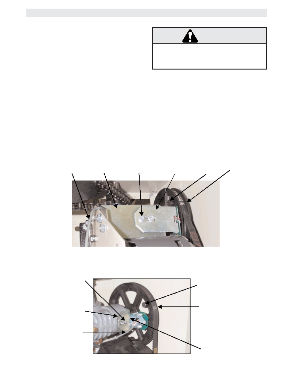
HALL EFFECT SENSOR ADJUSTMENT
NOTE: Normally the Hall Effect sensor does not
need adjustment, but may go out of alignment due to
shipping vibration or rough handling.
These operators use an internal entrapment protec-
tor system. This system consists of the GL control
board, magnet, and Hall Effect sensor. It may
become necessary to adjust the sensor for correct
alignment. To do so please perform the following
steps:
1. Loosen the two screws holding the hall bracket to
the frame.
2. Adjust the hall effect bracket so that the hall effect
board is:
a. Parallel with the pulley.
b. .020" away from the pulley's magnet. Use
a feeler gauge to measure the distance.
TO AVOID SERIOUS PERSONAL INJURY OR
DEATH DISCONNECT ELECTRIC POWER
BEFORE ADJUSTING HALL EFFECT.
WARNING
CAUTION
WARNING
WARNING
3. Tighten screws to secure assembly.
4. Manually rotate pulley to ensure that each mag-
net clears the hall effect board.
If a magnet does not clear the board, re-adjust the
hall effect assembly accordingly.
Hall Effect
Cable
Mounting
Bracket
Mounting
Screw (2)
Hall Effect
Bracket
Pulley
Magnet
Pulley
Hall Effect
Cable
Mounting
Bracket
Mounting
Screw (2)
Hall Effect
Bracket
Pulley
Magnet
Pulley