Disconnect switch power wiring, Stop/reset button control wiring (required) – Controlled Products Systems Group SW4705011G3 User Manual
Page 15
15
Important: On three phase operators, power connec-
tions must be properly phased. If phased incorrectly,
the gate operator will run reversed. To correct this sit-
uation, shut off power at main power source and at the
operators electrical disconnect switch. Then reverse
any two of the three power leads.
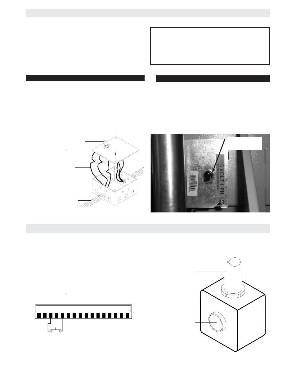
DISCONNECT SWITCH POWER WIRING
STOP/RESET BUTTON CONTROL WIRING (REQUIRED)
Cover
ON/OFF Switch
Wire Nut Connections
(See Instructions)
Power Wiring Conduit
NOTE: Before running power wiring refer to wiring
specifications on page 14 for correct wire gauges.
Secure all electrical power connections inside the dis-
connect switch electrical box. Refer to electrical wiring
diagram on pages 33, 34 and 35.
1. This control will function as a Stop/Reset com-
mand and is to be wired within line of sight of the
gate. The operator will not function unless this
circuit is completed.
2. Wire control station to terminals 3 and 5 in the
control box on the operator.
J1 CONNECTOR
NOTE: For additional control station options refer to
pages 18 & 19.
STOP/RESET
Button
Control Conduit
STOP/RESET
STOP/RESET BUTTON WIRING
1 2 3 4 5 6 7 8 9 10 11 12 13 14 15 16
DISCONNECT
SWITCH
All single phase operators will have the following:
115V 208/230V
L1 (NEUTRAL), WHITE
L1 (HOT), BLACK
L2 (HOT), BLACK
L2 (HOT), BLACK
GROUND, GREEN
GROUND, GREEN
SINGLE PHASE
THREE PHASE
All three phase operators will have the following:
L1 (HOT), BLACK
L2 (HOT), BLACK
L3 (HOT), BLACK
GROUND, GREEN