Radio receiver instructions (412hm to gl operator), Limit switch adjustment, Caution – Controlled Products Systems Group SW4705011G3 User Manual
Page 16: Limit direction
16
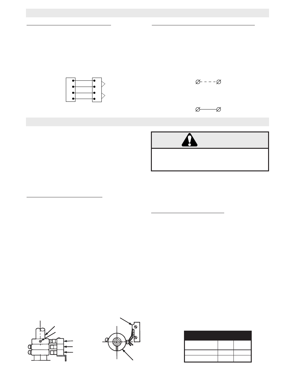
LIMIT SWITCH ADJUSTMENT
DIRECTION OF
GATE TO OPEN
RIGHT
LEFT
OPEN
LIMIT
A
B
CLOSE
LIMIT
B
A
LIMIT DIRECTION
DRIVE SHAFT
SET SCREW
AUX. SWITCH
(OPTIONAL)
LIMIT SWITCH “A”
LIMIT SWITCH “B”
LIMIT SWITCH
LIMIT CAM
CAUTION
NEVER PLACE HANDS OR TOOLS INSIDE OPERA-
TOR OR NEAR DRIVE MECHANISM UNLESS
POWER IS OFF.
RADIO RECEIVER INSTRUCTIONS (412HM TO GL OPERATOR)
NOTE: For limit location and configuration refer to figure
1
1. Before turning on power, disconnect extension arm
from gate bracket so gate is no longer connected to oper-
ator.
2. The (3) collars are held to shaft by set screws. The
collars should now be loose on the shaft. If not, loosen
all set screws until collars are moving freely on shaft.
TO ADJUST CLOSE LIMIT SWITCH
3. Turn on electrical power.
4. Press CLOSE button (if installed) or connect terminals
4 & 5 on J1 terminal strip to cause the gate to close. The
control arm should move in the close direction.
5. When control arm is pointed in approximate direction
of gate bracket (on fully closed gate) press STOP button
or release terminals to stop control arm.
NOTE: If control arm does not move far enough to point
in proper direction, the close limit switch has been pre-
maturely actuated. Turn off power, loosen set screw on
close limit cam and rotate nut away from close limit
switch. Repeat steps 3 & 4 until control arm is pointed in
correct direction.
6. Turn off power. Be sure close limit cam is freely turn-
ing. Rotate cam in close direction. Stop when cam just
clicks close limit switch. Tighten set screw.
7. Reconnect gate bracket to extension arm. If arm has
moved too far in close direction to allow connection of gate
bracket turn off power, connect terminals 5 & 7 to rotate
arm in opposite direction, and press STOP button when
arm is in desired position.
TO ADJUST OPEN LIMIT SWITCH
8. Turn on power. Press OPEN button (if installed) or con-
nect terminals 5 & 7 on J1 terminal strip. Gate should
open. If gate does not open the open limit cam may be
already actuating open limit switch or an improper electri-
cal connection may have been made. Turn off power,
inspect, correct and repeat this step.
9. When gate reaches desired fully open position press
STOP button or release terminals. Turn off power. Limit
cam should turn freely. Rotate cam in open direction.
Stop when cam just clicks the open limit switch. Tighten
set screw.
10. Fine tune both switch settings by using J1 terminals 4
& 5 (to CLOSE) of 5 & 7 (to OPEN) and the factory sup-
plied STOP button to move gate and rotating limit collars
slightly to alter gate travel. Rotate cam away from limit
switch to increase travel, toward switch to decrease trav-
el.
412HM to Operator Wiring Instructions
1. For Receiver Power, wire 412HM receiver terminal 1
to GL operator terminal R1 and receiver terminal 2 to
operator terminal R2.
2. For Receiver Relay Control, wire 412HM receiver ter-
minal 3 (relay) to GL operator terminal R3 and receiver
terminal 4 (common) to operator terminal R4.
R1
R2
R3
R4
1
2
3
4
GL OPERATOR
412HM
RECEIVER
24 VAC
RELAY
Receiver Commercial/Residential Radio Function
NOTE: SW470/SW490 operators are factory wired for
commercial radio applications. This means that the R3 &
R4 terminal cause the operator to open only when acti-
vated. To give a radio control single button operation
(Residential radio application) perform the following.
1. Locate and disconnect the end of the wire running to
terminal J1-6 from R4.
2. Connect end of wire removed from J1-6 to J1-1.
R4
J1-6
ON
ON
R4
J1-1
1
ON