Parts diagram – Controlled Products Systems Group I8 User Manual
Page 4
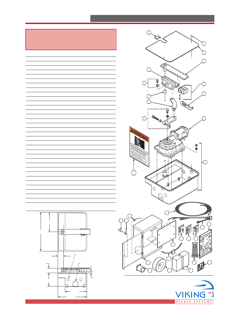
Overall Dimensions
Weight 65
lb.
TECHNICAL SUPPORT 1 800 908 0884
i
PARTS DIAGRAM
PARTS DIAGRAM
9
1
2
4
5
8
(4)
(2)
(4)
(4)
12
7
3
11
6
10
13
29
I
tem Description
Part No.
1
Cover
I8CV
2
Gate Attachment
I8GATT
3
Intermediate Drive Arm
I8IDRAM
4
Manual Release Mechanism
I8LCKMN
5
Manual Release Key
I8MNRKY
6
Secondary Drive Arm
I8SDA
7
Primary Drive Arm with Hardware
I8PDRARM
8
Gearmotor Assembly
I8GMA
9
Casing with Hardware
I8CH
10
Ball Bearing
I8BB
11
Plastic Gap Filler
I8PGF
12
I8 Cover Holder Hardware
I8CVHW
13
I8 Positive Stop Hardware Open
I8PSHO
14
I8 Positive Stop Hardware Close
I8PSHC
15
Optional Stainless Steel Casing and Cover
I8CSSH
13
ECU Box
VA-ECUBB
14
Control Board (Single/Master-Slave) DUPCB10-I8/DUMSCB10-I8
15
Mounting Plate (Single/Master-Slave) ECUMPS10 / ECUMPMS10
16
Toroid Transformer, 10 awg
DUTT10
17
EMI Board
DUEMI10
18
Battery DUBA12
19
Battery Fuse Holder
VABFH
20
Motor Harness
ECUMTHRN
21
Power Harness
DUPHC
22
Alarm
DUAL10
23
ECU Access Key
ECUKEY
24
ECU Key Cylinder
ECUKEYC
25
Reset Switch
ECURW
26
Fuse Kit
DUFSK10
27
Radio Antenna Kit
VARAK
28
Strain Relief
DH3/4NMCC
29
Warning Placard
DUWPA
30
7-Conductor Cable, 16 ga.
VA-CB16
9.375"
2.56"
13.46"
8.31"
6.61"
2.24"
Approx.
0.59" Gap
16.61"
1.375" Electrical
Knock-out (2) places
both sides
Drain Opening
WARNING - For Installation
By Qualified Personnel Only.
24
25
23
14
21
17
18
30
16
13
22
26
15
27
19
20
28