Installation details, Step 5, Step 6 – Controlled Products Systems Group I8 User Manual
Page 15: Step 7, Step 8
TECHNICAL SUPPORT 1 800 908 0884
11
INSTALLATION DETAILS
INSTALLATION DETAILS
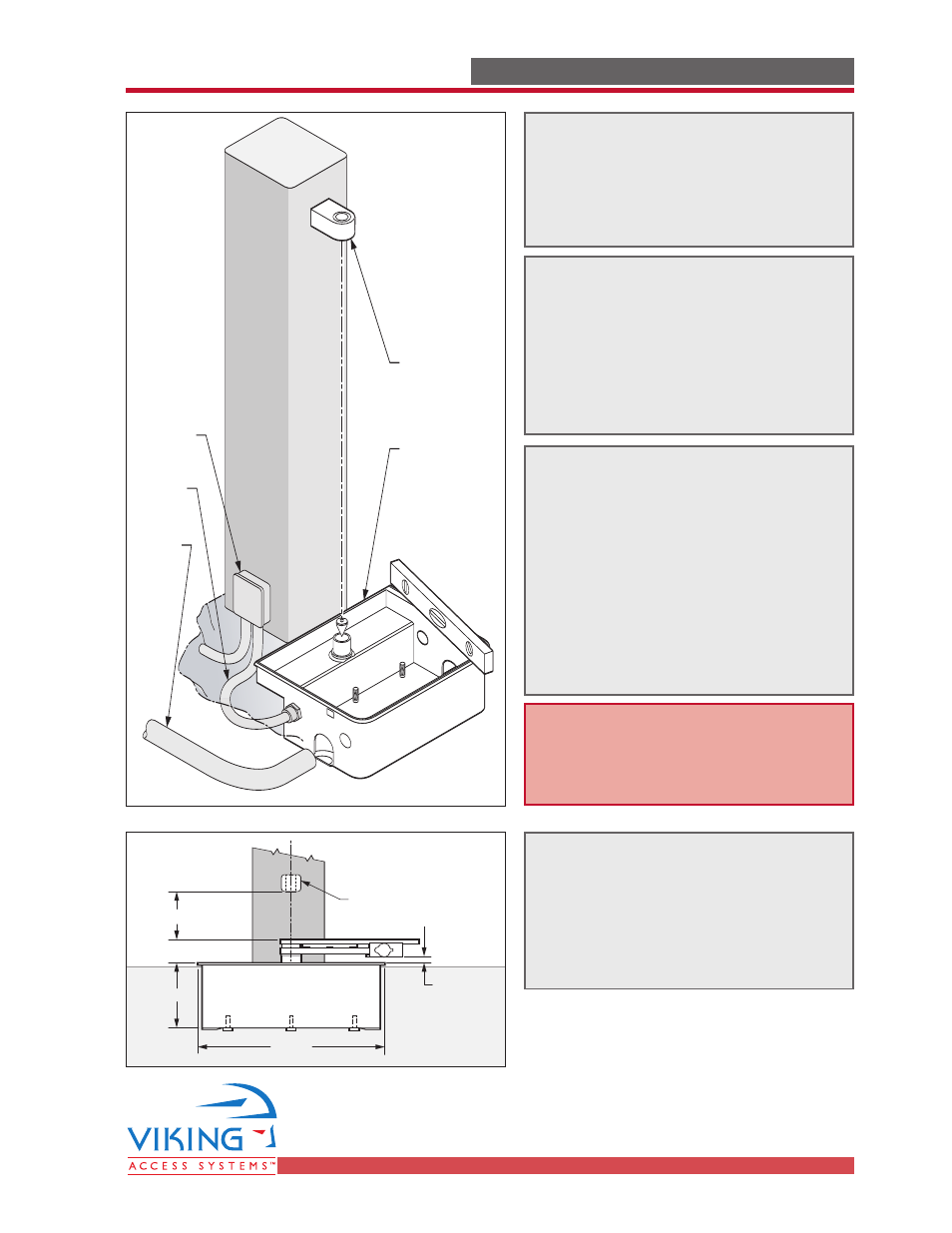
Positive
Drainage
Electrical
Conduit
Electrical
Junction Box
Upper Hinge
Must Line Up
with Hinge in
Foundation
Casing
Foundation
Casing Must
Be Set Level In
Both Directions
16.60"
6.60"
2.25"
5" (minimum)
Approx.
0.60" Gap
Lower Hinge
(optional)
STEP 5
Prepare for the wiring using
conduit suited for underground
application. Route the the conduit
to an above ground junction box.
STEP 6
Run a flexible drain pipe from the
Gate Operator to an area drain.
Ensure that the pipe has proper
slope to prevent any water
accumulation in the operator or
adjacent area.
STEP 7
Ensure the Gate Operator is level in
both directions and that the
Articulation Point is properly
aligned. Fill the area with concrete
and level off approximately 0.200”
below the top of the Operator
Casing. Before the concrete is fully
cured, check for level and
alignment again.
STEP 8
An additional (lower) hinge can be
installed. This hinge must be
precisely aligned between the
Upper Hinge and the Articulation
Point in the Gate Operator.
Note: Once the concrete is set you
will not be able to change the
level or alignment of the Gate
Operator.