For viking vehicular gate operators – Controlled Products Systems Group I8 User Manual
Page 34
TECHNICAL SUPPORT 1 800 908 0884
30
OPTIONALSOLAR PANEL INSTALLATION
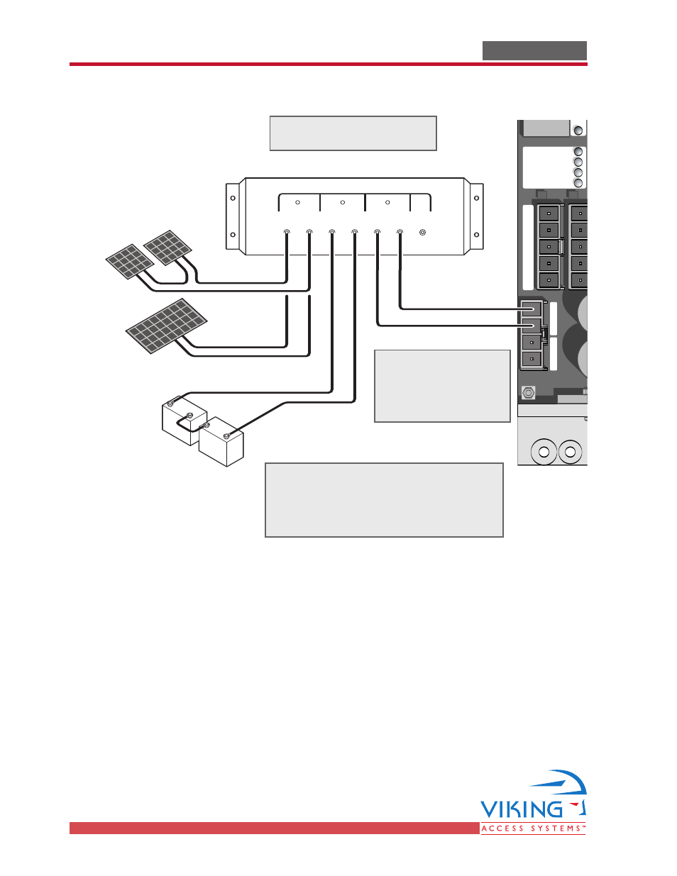
OPTIONAL SOLAR PANEL INSTALLATION
For Viking Vehicular Gate Operators
Radio Station
Mag.
Lock
M
a
g
. L
o
ck
Safety Connector
Open Commands
Guard Station
Master/Slave
Brake
UL
Siren
Radio
Rec.
UL
Sensor
O
P
E
N
R
IG
H
T
2
4
V
B
A
T
2
4
V
A
C
O
P
E
N
L
E
FT
Safety
Loop
Center
Loop
Obstruction
Sensor
Charger
Power
Low Battery
Motor Sensor
Hold Open
Timer
Stop
Overlap Delay
Close
Open
O
b
st
ru
ct
io
n
S
e
n
so
r
min.
MAX
O
ve
rla
p
D
e
la
y
1.5
0
3
Radio Station
Loop Connector
Open Commands
Guard Station
Master/Slave
G
N
D
C
lo
se
S
to
p
O
p
e
n
G
N
D
C
lo
se
S
to
p
O
p
e
n
G
n
d
Fir
e
G
n
d
S
tri
k
e
G
n
d
Ex
it
G
n
d
C
e
n
te
r
G
n
d
Re
op
en
G
n
d
U
L
G
n
d
+
2
8
v
G
n
d
R
a
d
io
G
n
d
+
2
8
v
+
2
8
v
M
a
g
.
Lo
ck
Fail
Safe/Secure
M
A
G
. L
O
C
K
N.C.
COM
N.O.
Charger
Power
Low Battery
Check Motor
H
o
ld
O
p
e
n
Tim
e
r
S
to
p
C
lo
se
O
p
e
n
3
0
6
0
O
ff
1
R
a
d
io
R
e
c.
U
L
S
e
n
s
R
e
o
p
e
n
Lo
o
p
C
e
n
te
r
Lo
o
p
B
ra
ke
Sir
en
JP3
C35
C36
+
–+
–+
–
+
–
+
–
Solar Input Battery Input Load Input
Connect the Solar Panel
Controller as shown.
Remove existing batteries. Use new
external batteries of 35 AHr or
greater and connect them in series to
provide a 24V system.
Remove the existing
Power Harness and
use the power
harness provided.