Plan of installation, Inside outside, Step 1 – Controlled Products Systems Group I8 User Manual
Page 14: Step 2, Step 3, Step 4
TECHNICAL SUPPORT 1 800 908 0884
10
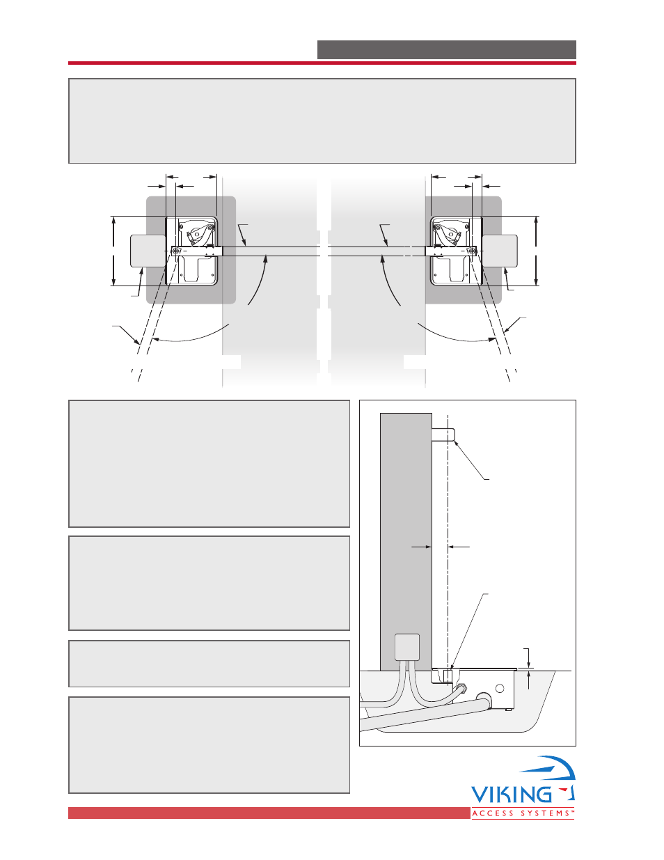
PLAN OF INSTALLATION
PLAN OF INSTALLATION
The gate must be installed in a location so that enough clearance is supplied
between the gate and adjacent structures when opening and closing to reduce the
risk of entrapment.
Swinging gates shall not open into public access areas.
2.56"
Hinge
Foundation
Casing Hinge
Approx.
0.20"
Inside
Outside
Gate in
Closed
Position
110
°
Maximum
Gate in
Open Position
Gate Support
Column
2.56"
13.46"
16.61"
Gate in
Closed
Position
110
°
Maximum
Gate in
Open Position
Gate Support
Column
2.56"
13.46"
16.61"
STEP 1
Ensure the center of the Upper Hinge is 2.56”
from mounting surface. Weld in place.
If the hinge center is less than 2.56” form the
surface, clearance will have to cut into the lower
mounting surface to allow the center of the
articulation point to align to the hinge used.
STEP 2
Use a Plumb Bob and mark a center reference for
the Articulation Point of the Gate Operator. This will
show approximately how much area will need to
be worked to inground the unit.
STEP 3
Mark the area to be worked.
STEP 4
Remove the dirt or concrete and prepare the
surface area for the Gate Operator. Ensure the
operator will sit level and that the Articulation
Point will be aligned with the Upper Hinge.
Gate Operator
Opens Right
Gate Operator
Opens Left