Optional viking blue installation, Hold open timer stop close open o b st ru ct io n, Ma g . lo ck – Controlled Products Systems Group I8 User Manual
Page 33: Match up
TECHNICAL SUPPORT 1 800 908 0884
29
OPTIONAL VIKING BLUE INSTALLATION
OPTIONAL VIKING BLUE INSTALLATION
Radio Station
Safety Connector
Open Commands
Guard Station
Master/Slave
Brake
UL
Siren
O
P
E
N
R
IG
H
T
2
4
V
B
A
T
2
4
V
A
C
O
P
E
N
L
E
FT
Hold Open
Timer
Stop
Close
Open
O
b
st
ru
ct
io
n
S
e
n
so
r
min.
MAX
O
ve
rl
a
p
D
e
la
y
1.
5
0
3
Radio Station
Loop Connector
Open Commands
Guard Station
Master/Slave
G
N
D
C
lo
se
S
to
p
O
p
e
n
G
N
D
C
lo
se
S
to
p
O
p
e
n
G
n
d
Fi
re
G
n
d
S
tr
ik
e
G
n
d
Ex
it
G
n
d
C
e
n
te
r
G
n
d
Re
op
en
G
n
d
U
L
G
n
d
+
2
8
v
G
n
d
R
a
d
io
G
n
d
+
2
8
v
+
2
8
v
M
a
g
.
Lo
ck
Fail
Safe/Secure
M
a
g
.
Lo
ck
M
A
G
.
LO
C
K
N.C.
COM
N.O.
Charger
Power
Charger
Power
Low Battery
Check Motor
H
o
ld
O
p
e
n
Ti
m
e
r
S
to
p
C
lo
se
O
p
e
n
3
0
6
0
O
ff
1
R
a
d
io
R
e
c.
U
L
S
e
n
s
R
e
o
p
e
n
Lo
o
p
C
e
n
te
r
Lo
o
p
B
ra
ke
Si
re
n
JP3
C35 C36
1. Insert CD into host computer
2. Install MS ActiveSync (
check your
computer, it may already be installed
to
communicate with a PDA or smart phone.
3. Install Viking Blue software
Select Install Viking-Blue for PC (to have the
computer to communicate with the Operator)
Select Install Viking-Blue for PDA (to have
the PDA to communicate with the Operator)
WARNING: If this PDA is a new device, turn off
all options when syncing with the computer.
For either installation, follow the steps in the
user manual.
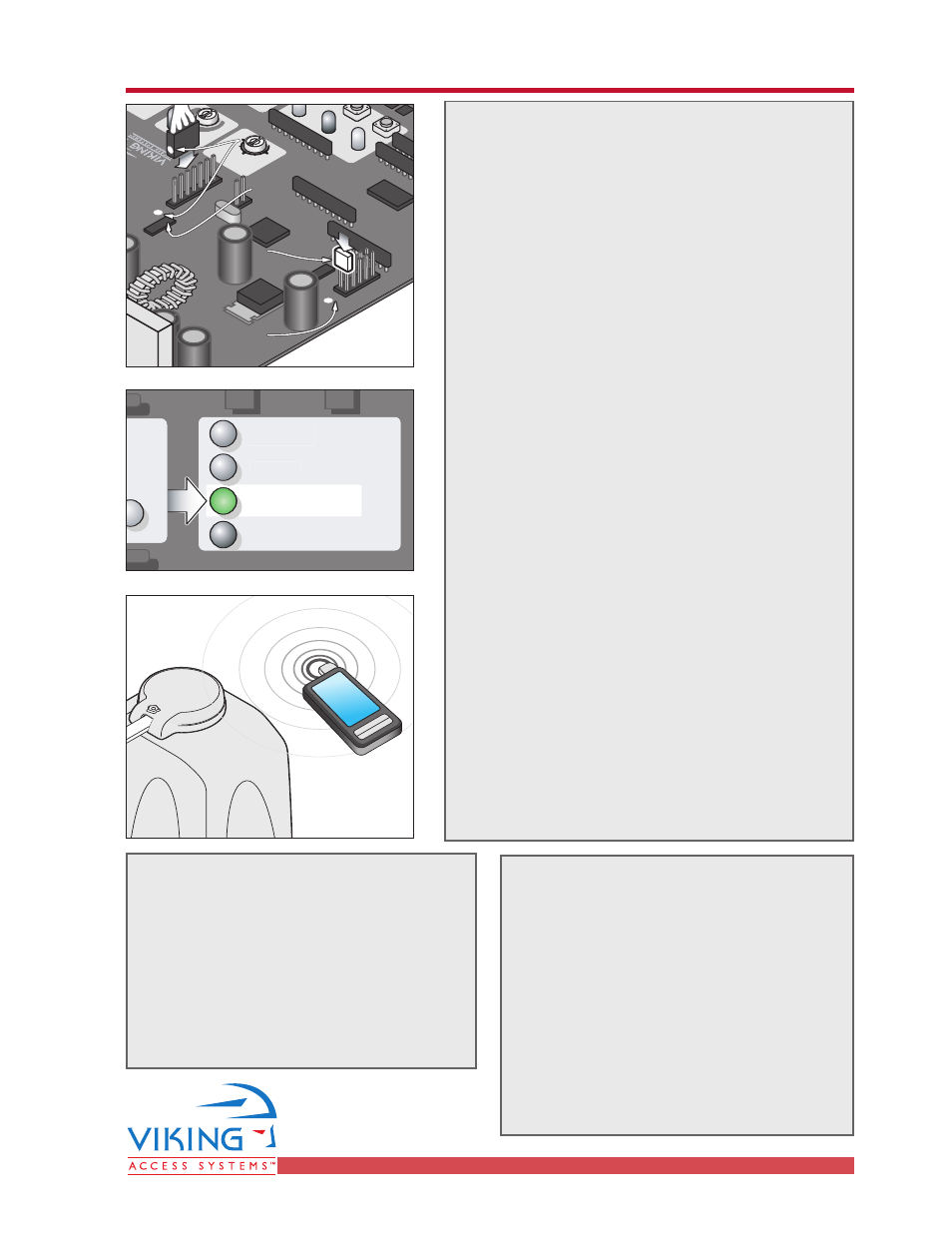
4. Plug the Viking Blue Module into the Viking
Gate Operator Control Board.
WARNING: Connecting the plug backwards can
result in damage to the Control Board and
will render the Viking Blue Module useless.
Use care in connecting the plug to the Control
Board. The pins are small and easily bent.
Match the white dot on the plug to the white
dot on the control board (near the JP2 legend
as depicted).
5. Install the Jumper (near the JP3 legend
depicted). Viking-Blue requires this jumper
to operate. The “Low Battery” LED will turn
ON, indicating the Control Board is ready for
use with the Viking-Blue Module.
6. Open Viking Blue software on the chosen
device.
If you are using the computer:
• Hold the computer near the Gate
Operator.
• Run the application by clicking the
icon on the desktop.
• Select “Setting” in the top right of the
screen.
If you are using a PDA:
• Hold the PDA near the Gate Operator.
• Select “Start” and “Programs”.
• Click the Viking-Blue Application.
• Select “Connection” on the toolbar.
• Click “Search” (looking for available
Viking devices).
• Select the Operator you want to
communicate with.
• Click “Connect” to start communication.
The Light on the Viking-Blue module
will turn green upon connection to the
Computer or PDA.
Follow the steps in the user manual.
Ra
dio
St
ati
on
Op
en
C
om
ma
nd
s
Gu
ard
St
ati
on
Ma
ste
r/S
la
ve
OPE
N R
IG
HT
24V
B
AT
24V
AC
OPE
N LE
FT
Ch
arg
er
Po
we
r
Low
B
att
ery
Obs
tru
ctio
n
Se
nso
r
mi
n.
mi
n.
mi
n.
MA
X
Ove
rla
p
Dela
y
1.5
1.5
0
3
3
Ra
dio
St
ati
on
Loo
p C
on
ne
cto
r
Op
en
C
om
ma
nd
s
Gu
ard
St
ati
on
Ma
ste
r/S
la
ve
GN
D
Clos
e
Sto
p
Ope
n
GN
D
Clos
e
Sto
p
Ope
n
Gnd
Fire
Gnd
Strik
e
Gnd
Exit
Gnd
Cen
ter
Gnd
Reo
pen
Gnd
UL
Gnd
+28
v
Gnd
Rad
io
Gnd
+28
v
+28
v
Ma
g.
Loc
k
Fa
il
Sa
fe/
Se
cu
re
MA
G. L
OCK
N.C
.
CO
M
N.O
.
Ch
arg
er
Po
we
r
Low
B
att
ery
Ch
ec
k M
oto
r
Hold
O
pen
Tim
er
Sto
p
Sto
p
Clos
e
Ope
n
Ope
n
30
60
Off
1
Rad
io
Rec
.
UL
Sen
s
Reo
pen
Loo
p
Cen
ter
Loo
p
Bra
ke
Sire
n
JP3
C3
5
C3
6
JP2
Match up
Match up
White Dots
White Dots
Match up
White Dots
Install
Install
Jumper
Jumper
Install
Jumper
JP3
JP3
JP3
JP2
JP2
JP2