Accessory connections, Guard station, Magnetic lock solenoid connection – Controlled Products Systems Group I8 User Manual
Page 29: Connection locations (single unit board shown)
TECHNICAL SUPPORT 1 800 908 0884
26
24
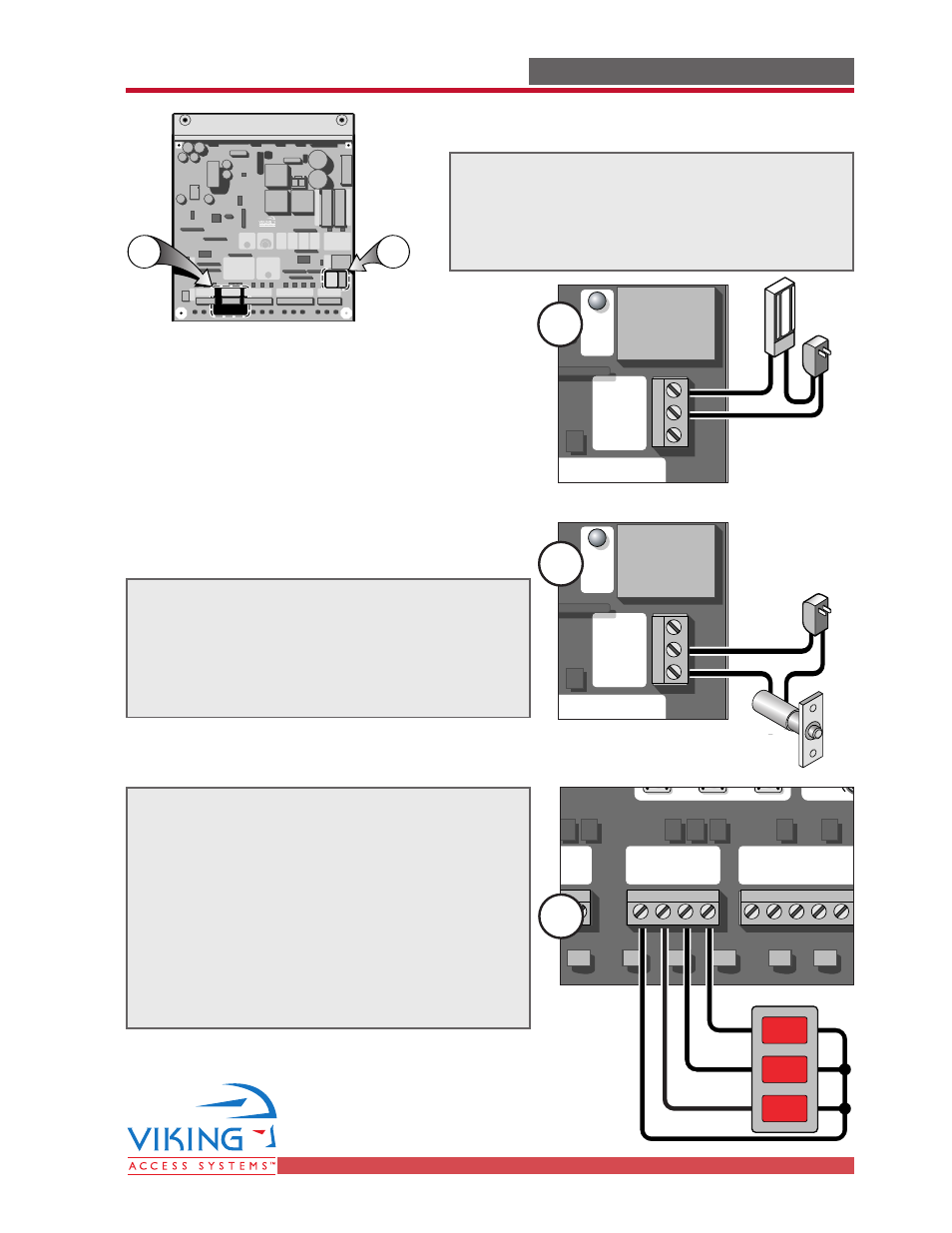
The guard station provides control of the
gate operator to open, stop and close the
gate.
All three switches must be Normally Open
type of switch, and can share the same
common (ground).
Place the control switch box within sight of
the gate, away from moving parts of the
gate and out of reach of children.
Guard Station
Radio Station
Mag.
Lock
M
a
g
.
Lo
ck
Safety Connector
Open Commands
Guard Station
Master/Slave
Brake
UL
Siren
Radio
Rec.
UL
Sensor
O
P
E
N
R
IG
H
T
2
4
V
B
A
T
2
4
V
A
C
O
P
E
N
L
E
FT
Safety
Loop
Center
Loop
Obstruction
Sensor
Charger
Power
Low Battery
Motor Sensor
Hold Open
Timer
Stop
Overlap Delay
Close
Open
O
b
st
ru
ct
io
n
S
e
n
so
r
min.
MAX
O
ve
rl
a
p
D
e
la
y
1.
5
0
3
Radio Station
Loop Connector
Open Commands
Guard Station
Master/Slave
G
N
D
C
lo
se
S
to
p
O
p
e
n
G
N
D
C
lo
se
S
to
p
O
p
e
n
G
n
d
Fi
re
G
n
d
S
tr
ik
e
G
n
d
Ex
it
G
n
d
C
e
n
te
r
G
n
d
Re
op
en
G
n
d
U
L
G
n
d
+
2
8
v
G
n
d
R
a
d
io
G
n
d
+
2
8
v
+
2
8
v
M
a
g
.
Lo
ck
Fail
Safe/Secure
M
A
G
.
LO
C
K
N.C.
COM
N.O.
Charger
Power
Low Battery
Check Motor
H
o
ld
O
p
e
n
Ti
m
e
r
S
to
p
C
lo
se
O
p
e
n
3
0
6
0
O
ff
1
R
a
d
io
R
e
c.
U
L
S
e
n
s
S
a
fe
ty
Lo
o
p
C
e
n
te
r
Lo
o
p
B
ra
ke
Si
re
n
JP3
C35 C36
N.O.
N.O.
N.O.
COM
CLOSE
STOP
OPEN
2
External supply for the magnetic lock must
be provided. This will prevent rapid drainage
of the battery in the event of power failure.
Relay Contact 10A-250VAC
External supply for the solenoid connection
must be provided. This will prevent rapid
drainage of the battery in the event of
power failure.
Relay Contact 10A-250VAC
Magnetic Lock
Solenoid Connection
ACCESSORY CONNECTIONS
ACCESSORY CONNECTIONS
Radio Station
Mag.
Lock
M
a
g
.
Lo
ck
Safety Connector
Open Commands
Guard Station
Master/Slave
Brake
UL
Siren
Radio
Rec.
UL
Sensor
O
P
E
N
R
IG
H
T
2
4
V
B
A
T
2
4
V
A
C
O
P
E
N
L
E
FT
Safety
Loop
Center
Loop
Obstruction
Sensor
Charger
Power
Low Battery
Motor Sensor
Hold Open
Timer
Stop
Overlap Delay
Close
Open
O
b
st
ru
ct
io
n
S
e
n
so
r
min.
MAX
O
ve
rl
a
p
D
e
la
y
1.
5
0
3
Radio Station
Loop Connector
Open Commands
Guard Station
Master/Slave
G
N
D
C
lo
se
S
to
p
O
p
e
n
G
N
D
C
lo
se
S
to
p
O
p
e
n
G
n
d
Fi
re
G
n
d
S
tr
ik
e
G
n
d
Ex
it
G
n
d
C
e
n
te
r
G
n
d
Re
op
en
G
n
d
U
L
G
n
d
+
2
8
v
G
n
d
R
a
d
io
G
n
d
+
2
8
v
+
2
8
v
M
a
g
.
Lo
ck
Fail
Safe/Secure
M
A
G
.
LO
C
K
N.C.
COM
N.O.
Charger
Power
Low Battery
Check Motor
H
o
ld
O
p
e
n
Ti
m
e
r
S
to
p
C
lo
se
O
p
e
n
3
0
6
0
O
ff
1
R
a
d
io
R
e
c.
U
L
S
e
n
s
S
a
fe
ty
Lo
o
p
C
e
n
te
r
Lo
o
p
B
ra
ke
Si
re
n
JP3
C35 C36
Radio Station
Mag.
Lock
M
a
g
.
Lo
ck
Safety Connector
Open Commands
Guard Station
Master/Slave
Brake
UL
Siren
Radio
Rec.
UL
Sensor
O
P
E
N
R
IG
H
T
2
4
V
B
A
T
2
4
V
A
C
O
P
E
N
L
E
FT
Safety
Loop
Center
Loop
Obstruction
Sensor
Charger
Power
Low Battery
Motor Sensor
Hold Open
Timer
Stop
Overlap Delay
Close
Open
O
b
st
ru
ct
io
n
S
e
n
so
r
min.
MAX
O
ve
rl
a
p
D
e
la
y
1.
5
0
3
Radio Station
Loop Connector
Open Commands
Guard Station
Master/Slave
G
N
D
C
lo
se
S
to
p
O
p
e
n
G
N
D
C
lo
se
S
to
p
O
p
e
n
G
n
d
Fi
re
G
n
d
S
tr
ik
e
G
n
d
Ex
it
G
n
d
C
e
n
te
r
G
n
d
Re
op
en
G
n
d
U
L
G
n
d
+
2
8
v
G
n
d
R
a
d
io
G
n
d
+
2
8
v
+
2
8
v
M
a
g
.
Lo
ck
Fail
Safe/Secure
M
A
G
.
LO
C
K
N.C.
COM
N.O.
Charger
Power
Low Battery
Check Motor
H
o
ld
O
p
e
n
Ti
m
e
r
S
to
p
C
lo
se
O
p
e
n
3
0
6
0
O
ff
1
R
a
d
io
R
e
c.
U
L
S
e
n
s
S
a
fe
ty
Lo
o
p
C
e
n
te
r
Lo
o
p
B
ra
ke
Si
re
n
JP3
C35 C36
2
1
1
1
Connection Locations
(Single Unit Board shown)