Gate operator installation – Controlled Products Systems Group I8 User Manual
Page 17
TECHNICAL SUPPORT 1 800 908 0884
13
17
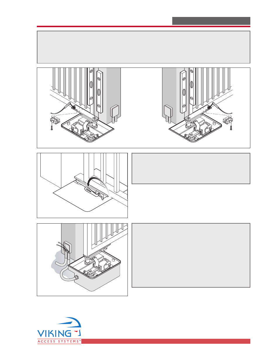
GATE OPERATOR INSTALLATION
GATE OPERATOR INSTALLATION
STEP 14
Lock the Manual Release Mechanism (so that
the gate is engaged with the Gate Operator).
STEP 15
Route the wires for the Gearmotor through
the conduit already in place. Connect the
two wires to the wires coming from the
Control Board.
The Wires are color coded:
Black to Black
Blue to Blue
STEP 13
Install the Gate Attachment to the Intermediate Drive Arm. Mount the gate on the
hinge(s) and verify its alignment with the hinge(s) and Articulation Point. Weld the
gate to the Gate Attachment.
See also other documents in the category Controlled Products Systems Group Safety:
- GNC-1 (1 page)
- -108712 (33 pages)
- 1044372 (28 pages)
- 1042071277 (28 pages)
- 104207177 (28 pages)
- 104301 (30 pages)
- 10441811 (29 pages)
- 1044182 (28 pages)
- 1044682 (28 pages)
- 104471 (28 pages)
- 104572 (27 pages)
- 104572 (24 pages)
- 10468583 (36 pages)
- 1049062 (17 pages)
- 106753 (28 pages)
- 108758 (40 pages)
- 109773 (19 pages)
- 10978021 (6 pages)
- 109902 (27 pages)
- 1150-080 (30 pages)
- 1600 (17 pages)
- 1650ETL (23 pages)
- 1650ETL-1K (32 pages)
- 1601-081 (36 pages)
- 1602-091 (42 pages)
- 1602-091 (42 pages)
- 1603-166 (40 pages)
- 1603-166 (38 pages)
- 1603-166 (42 pages)
- 444 XS ST (98 pages)
- 222X383 (84 pages)
- 3020HX (24 pages)
- 3600ETL-1K (36 pages)
- 4500SW (32 pages)
- 6004-080 (34 pages)
- 6002-080 (32 pages)
- 6003-080 (22 pages)
- 6100-083 (56 pages)
- 6100-083 (2 pages)
- 6100-083 (46 pages)
- 6300-087 (59 pages)
- 6300-087 (52 pages)
- 6400-080 (28 pages)
- 6500-087 (48 pages)
- 6500-087 (46 pages)