Solar panel installation, For viking vehicular gate operators, Step 1 – Controlled Products Systems Group I8 User Manual
Page 35: Step 3, Step 2, Step 4
TECHNICAL SUPPORT 1 800 908 0884
31
SOLAR PANEL INSTALLATION
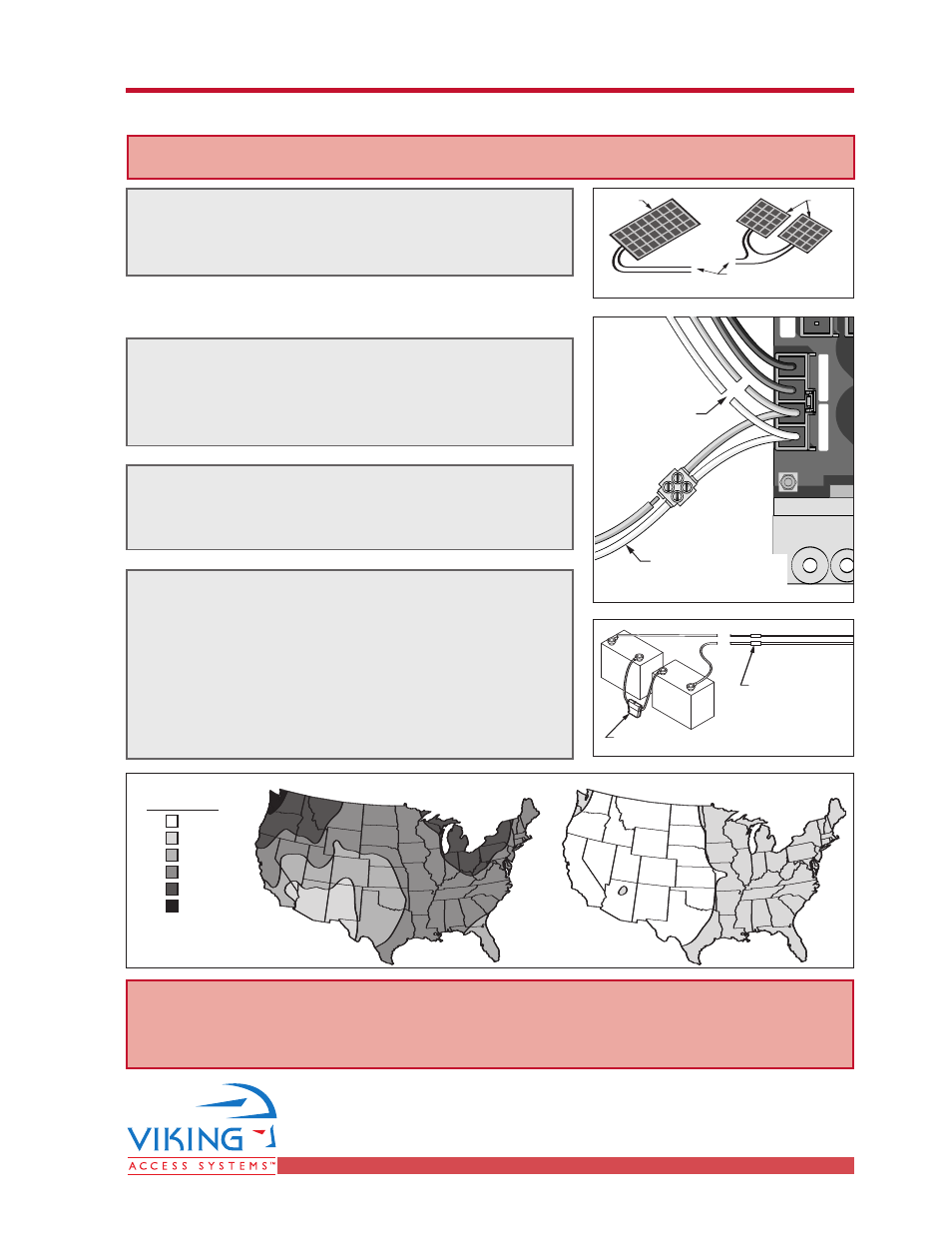
SOLAR PANEL INSTALLATION
For Viking Vehicular Gate Operators
STEP 1
Use a 24V solar panel or two solar panels of 12V
in series with a total capacity of 80 Watts..
STEP 3
Replace the existing batteries with a battery pack
of 35AHr or greater.
STEP 2
Connect the solar panel cables to the power
harness as shown. Make sure you cut the wires
coming from the toroidal transformer.
STEP 4
Refer to the maps provided to get an idea about the
number of cycles the gate will be operated per day.
This figure is for a single gate operator with just:
a) One Radio reiver,
b) One low voltage low current loop detector and
c) One low voltage, low current photo cell
Radio Station
Mag.
Lock
M
a
g
. L
o
ck
Safety Connector
Open Commands
Guard Station
Master/Slave
Brake
UL
Siren
Radio
Rec.
UL
Sensor
O
P
E
N
R
IG
H
T
2
4
V
B
A
T
2
4
V
A
C
O
P
E
N
L
E
FT
Safety
Loop
Center
Loop
Obstruction
Sensor
Charger
Power
Low Battery
Motor Sensor
Hold Open
Timer
Stop
Overlap Delay
Close
Open
O
b
st
ru
ct
io
n
S
e
n
so
r
min.
MAX
O
ve
rla
p
D
e
la
y
1.5
0
3
Radio Station
Loop Connector
Open Commands
Guard Station
Master/Slave
G
N
D
C
lo
se
S
to
p
O
p
e
n
G
N
D
C
lo
se
S
to
p
O
p
e
n
G
n
d
Fir
e
G
n
d
S
tri
k
e
G
n
d
Ex
it
G
n
d
C
e
n
te
r
G
n
d
Re
op
en
G
n
d
U
L
G
n
d
+
2
8
v
G
n
d
R
a
d
io
G
n
d
+
2
8
v
+
2
8
v
M
a
g
.
Lo
ck
Fail
Safe/Secure
M
A
G
. L
O
C
K
N.C.
COM
N.O.
Charger
Power
Low Battery
Check Motor
H
o
ld
O
p
e
n
Tim
e
r
S
to
p
C
lo
se
O
p
e
n
3
0
6
0
O
ff
1
R
a
d
io
R
e
c.
U
L
S
e
n
s
R
e
o
p
e
n
Lo
o
p
C
e
n
te
r
Lo
o
p
B
ra
ke
Sir
en
JP3
C35
C36
Connect Leads from
Solar Panel(s), Polarity
is not important
Cut the Leads
to the Toroidal
Transformer
+
–
+
+
–
–
Reuse Existing
Battery Fuse Holder
Connect New
Batteries to
Existing Leads
Observing Polarity
Red Wire
Black Wire
+
–
+
–
Connect To Gate
Operator Input Block
24 VDC
Panel
12 VDC
Panels
2
*With a 80 Watt (24VDC) Panel System.
5
8
10
12
14
Number of
Cycles per Day*
January
July
1. The greater capacity of the batteries, the longer the system will operate on cloudy days.
2. If more specific information is needed, please consult with Viking Access Systems.
For more information regarding solar energy refer to http:/www.nrel.gov.
W
WA
AR
RN
NIIN
NG
G –
– S
So
olla
arr P
Pa
an
ne
ell m
mu
usstt b
be
e U
UL
L L
Liisstte
ed
d,, C
Clla
assss 2
2