Controlled Products Systems Group 9050-080 User Manual
Page 28
9050-065-M-3-11
26
NC
NO
4702-010
12
11
10
9
8
7
6
5
4
3
2
1
NC
NO
4702-010
12
11
10
9
8
7
6
5
4
3
2
1
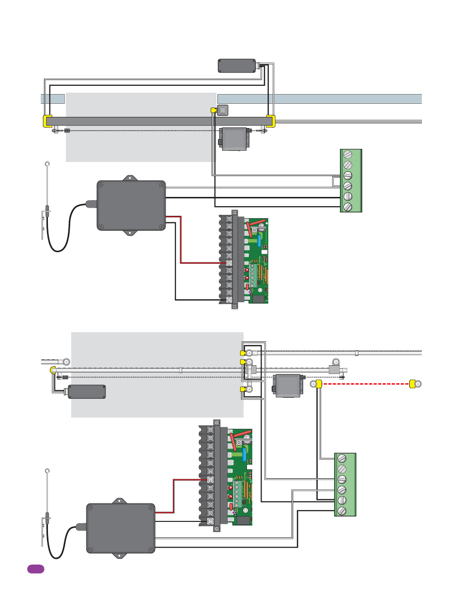
Wireless Reverse Edge Sample Setup - Single Receiver
Photo Sensor and Wireless Reverse Edge Sample Setup
Closed Gate
Wall
Normally Open
Common
Normally Open
Install Jumper Wire
Common
Normally Open
Normally Open
Common
When either direction reversing edge
get obstructed the gate will STOP, then
continue in the same direction after
obstructed reversing edge has been
cleared until the gate cycle is complete.
When a reversing edge or photo beam get
obstructed the gate will STOP, then continue
in the same direction after obstructed
reversing edge or photo beam has been
cleared until the gate cycle is complete.
Filler Post Note: Install reversing edges on all
the gate support posts or filler post in this area
(e.g. cantilever gate installations, See below).
Wireless Note: Refer to the
instruction sheet that comes
with the receiver/transmitter
for more specific wiring and
mounting instructions.
Closing-
Direction
Reversing
Edge
Closing-
Direction
Reversing
Edge
Opening-Direction Reversing Edge
6-Pin UL 325 Terminal Wiring
Opening-Direction Reversing Edge (If filler post is used).
9 V battery operated transmitter mounted on gate.
Filler Post
(If necessary)
Edge
Transmitter
Coax Antenna Kit
P/N 1514-073
Com
Com
Antenna mounted
outside operator cover.
24 VAC Receiver
Place receiver in operator.
6-Pin UL 325 Terminal Wiring
Normally Open
Normally Open
Common
Com
Opening-Direction Photo Beam
Normally Open
Common
Wireless Note: Refer to the
instruction sheet that comes
with the receiver/transmitter
for more specific wiring and
mounting instructions.
24 Volt
24 Volt
24 VAC Receiver
Place receiver in operator.
Photo Sensor Power Note:
Photo sensors can be powered
by the built-in convenience
outlets located on the operator
(See page 24).
Install Opening-Direction
reverse edges on the gate
support post(s) in this area.
Cantilever Gate
Coax Antenna
Kit
P/N 1514-073
Antenna mounted
outside operator
cover.
OPEN Entrapment Sensor
CLOSE Entrapment Sensor
OPEN Contact Sensor
CLOSE Contact Sensor
Low Voltage Common
Low Voltage Common
OPEN Entrapment Sensor
CLOSE Entrapment Sensor
OPEN Contact Sensor
CLOSE Contact Sensor
Low Voltage Common
Low Voltage Common
Power is
limited to
250 mamps.
Power is limited
to 250 mamps.
Main
Terminal
Main
Terminal
1
2
3
4
5
6
Edge
Transmitter
9 V battery operated
transmitter mounted on gate.
1
2
3
4
5
6