7 mounting operator and chain, Positioning operator and chain brackets – Controlled Products Systems Group 9050-080 User Manual
Page 19
9050-065-M-3-11
17
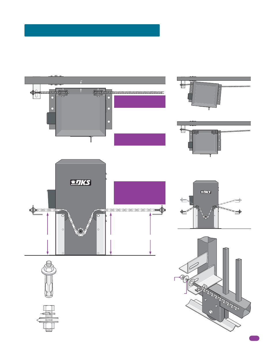
1.7 Mounting Operator and Chain
1” minimum from operator housing to gate.
Prior to mounting the operator, be sure that the correct chain knockouts have been removed and chain idler wheels are in the
correct position (top, center or bottom).
Fail-Secure Manual Release Kit Installation Note:
It is easier to install the 2600-862 fail-secure manual release kit before
mounting the operator and attaching the chain. Refer to the instruction sheet supplied with the kit for installation.
Operator MUST be parallel
to gate!
DoorKing recommends a
minimum of four (4) 3/8” x 2”
sleeve anchors (not supplied).
Use six (6) 1/2”-13 x 1 1/2”
bolts, lockwashers and nuts
(not supplied).
Operator NOT
parallel to gate.
Chain bracket
does NOT
align with
idler wheels.
Chain bracket MUST line up
with chain idler wheels!
Chain brackets MUST be
mounted so the chain
remains the same height
as it is on the idler wheels!
YES
YES
Positioning Operator and Chain Brackets
Attaching Operator
to Concrete
Attaching Operator
to Post Base Plate
Chain
Bracket
Lines up
with Idler
Wheels
Correct
Chain
Bracket
Height
Correct
Chain
Bracket
Height
Chain brackets
positioned
too high.
Chain brackets
positioned
too low.
Lock
Washer
Washers
Chain Idler Wheels
Chain Idler Wheels
3/8
YES
YES
NO
NO
NO
NO
NO
NO
Connect Chain Bracket
to Gate.
Weld completely
around bracket. Chain nut
and chain bolt should not
protrude past gate frame.
Connect chain to chain bolt with
master link. Adjust the chain nuts to
tighten the chain. The chain should sag no
more than one (1) inch per 10 feet of travel.
Do not over tighten the chain.
Connect Chain to Chain Bracket.
Chain
Nut
Chain Bolt
Chain Bracket
Option 2
Master
Link
Option 1
Gate
Frame
10.5”
10.5”
10.5”
Chain idler
wheels in
top position.