Settings / reverse sensitivity adjustment – Controlled Products Systems Group 6400-080 User Manual
Page 22
6400-065-E-05-07
22 6400
installation
guide
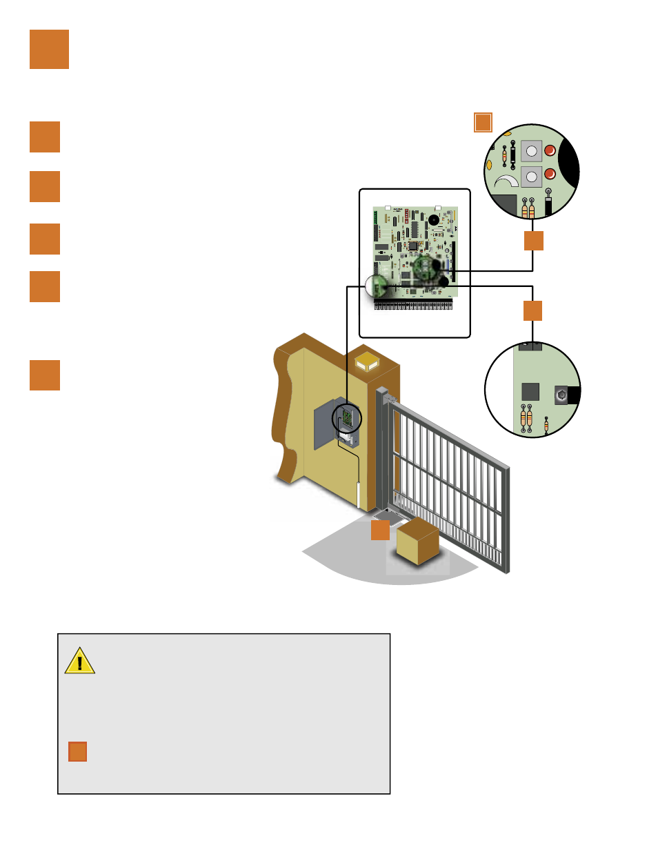
Activate the gate operator by pressing the
keyswitch button.
1
2
3
Operate the gate a few times to be sure that it
cycles completely.
While the gate is opening, slowly rotate the
Primary Reverse Sensitivity Sensor clockwise
until the gate reverses travel, back-off and reverse
the sensor 1/8 turn counter clockwise.
5
Actuators must be individually adjusted, repeat
steps 1-4 for the Secondary actuator if required
using the Secondary reverse sensitivity sensor.
Place an immobile object along the gate path, al-
lowing the gate to strike it while in the open or
close cycle. The gate must reverse direction after
striking the object. If it does not, increase the re-
verse sensitivity (refer to step 2) and repeat this
test. Repeat steps two (2) and four (4) until the
correct sensitivity has been set.
settings / reverse sensitivity adjustment
4
This vehicular gate operator is equipped with an inherent adjustable
reverse sensor (Type A) that is used as the primary entrapment
sensing system. When sensing an obstruction in either the opening
or closing gate cycle, the gate operator will reverse direction. For this system
to function correctly, the gate must be properly installed and work freely in
both directions. A good set of roller bearing hinges are essential for proper
swing gate operation.
Rotating the sensitivity sensor counter-clockwise DECREASES the
reverse sensitivity.
Rotating the sensitivity sensor clockwise INCREASES the reverse
sensitivity.
4
3,/
,)-)4
-/4/2
-/4/2
#/--/.
#/--/.
,)-)4
3,/
0HOTO
0HOTO
/PEN
#OMMON
#LOSE
#OMMON
37
-/4/2
-/4/2
2%$
#(!2'%$
#(!2').'
4)-%
$%,!9
'2%%.
2%3%4
#/092)'(4
$//2+).'
2%6%23%
%8)4
3%#/.$!29
1
9 10 11 12 13 14 15 16 17 18 19 20
#/-
0
+%9
37)4#(
+%9
37)4#(
1
2
4
1
1