Electrical installation / main terminal wiring – Controlled Products Systems Group 6400-080 User Manual
Page 14
6400-065-E-05-07
14 6400
installation
guide
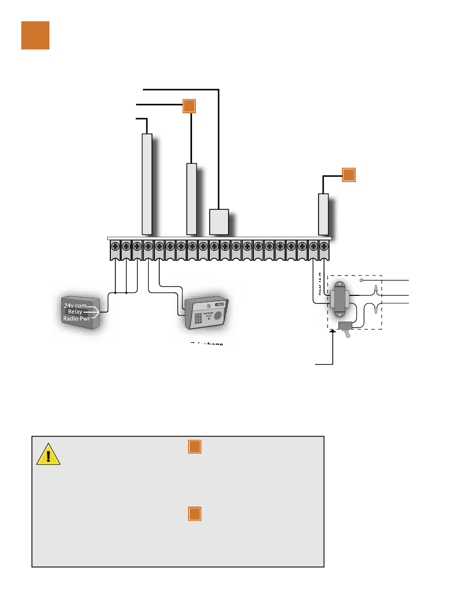
24V COMMON
RADIO RELA
Y
/ OPEN INPUT
24V DC RADI
O PWR
OPEN INPUT / EXIT LOOP
LOGIC
OUTPUT
24V COMMON
OPEN INPUT
24V COMMON
REVERSE / SHADOW INPUT
24V COMMON
RELA
Y
RELA
Y
24 VDC LOCK OUTPUT
24 VDC LOCK OUTPUT
NOT USED
12V BA
TT +
NOT USED
ALARM
RESET
24V COMMON
24 V
AC INPUT
24 V
AC INPUT
RED 12 A
W
G
BLACK
WHITE
GREEN
1
2
3
4
5
6
7
8
9
10
11
12
13
14
15
16
17
18
19
20
Telephone
115 VAC
Push Button
To Call
3-Wire
WHITE
BLACK
Function dependant on SW1, switch 3
Transformer enclosure
located in control box.
Wire nut 115 VAC input
power to Black and White
transformer wires.
Function dependant on SW1, switch 5
Function dependant on SW2, switch 1, 2
Controls must be far enough from the
gate so that the user is prevented from
coming in contact with the gate while
operating the controls. Outdoor or
easily accessible controls should have a
security feature to prevent unauthorized use.
When installing electrical equipment make
certain all wiring complies with local code
requirements.
Do not power any devices from the circuit
board other than a low voltage radio
receiver.
Reversing input (Terminal 8) only
functions while the gate is at the
full open position or during the closing
cycle should not be used as an input for a
secondary entrapment protection device
during the opening gate cycle. Refer to the
Secondary Entrapment Protection Device
Wiring section.
Connect optional control devices to
the main terminal strip. Use 18 AWG
wire for all low voltage wiring, maximum
distance 3000 feet. Use a low voltage surge
suppressor, (DoorKing P/N 1878-010) if low
voltage wire runs exceed 1000 feet. All inputs
to the terminal strip must be NORMALLY
OPEN.
electrical installation / main terminal wiring
3
1
2
1
2