Tb 1 tb 2 c nc no, Shadow loop – Controlled Products Systems Group 6400-080 User Manual
Page 18
6400-065-E-05-07
18 6400
installation
guide
SHA
DOW
LOO
P
3,/
,)-)4
-/4/2
-/4/2
#/--/.
#/--/.
,)-)4
3,/
02)-!29
+%9
37)4#(
1 2 3 4 5 6 7 8 9 10 11 12 13 14 15 16 17 18 19 20
3,/
,)-)4
-/4/2
-/4/2
#/--/.
#/--/.
,)-)4
3,/
0HOTO
0HOTO
/PEN
#OMMON
#LOSE
#OMMON
37
2%$
#(!2'%$
#(!2').'
4)-%
'2%%.
2%3%4
#/092)'(4
$//2+).'
2%6%23%
%8)4
3%#/.$!29
8 9 10 11
SHADOW
LOOP
LOOP DETECTOR
P/N 9405-010
TB 1 TB 2
C NC NO
SHADOW LOOP
electrical installation / shadow loop detector wiring
3
2
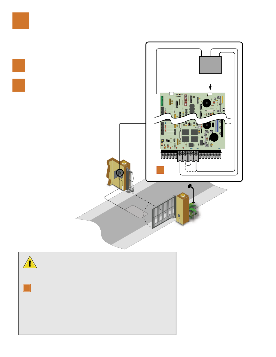
Route and connect the
SHADOW LOOP DETECTOR
cable as shown.
1
Disconnect power to the gate
operator before installing the
loop detector wiring.
A Shadow Loop is placed inside the swing gate area to prevent the gate from
closing on a vehicle that is in the path of the gate after the open time has
expired or the Exit Loop is too far back from the Reverse Loop. The Shadow
Loop is only active when the gate is in the full open position and will not allow the swing
gate to close. Once the close cycle begins the Shadow loop will not reverse the gate.
For correct SHADOW LOOP operation, jumper wire must be placed from terminal
9 to terminal 10. SW1 switch 5 must be OFF, SW2 switch 1 must be ON and SW2
switch 2 must be OFF.
Output of Shadow Loop Detector may be connected directly to terminals 8 and 9
(dotted line - no jumper required between 9 and 10) if SW 1, switch 5 is ON. However,
with this switch ON, terminal 8 becomes a shadow input (active only when the gate is
FULL OPEN) and all reversing devices connected to terminal 8 will operate as shadow
devices. If this is not desirable, wire the shadow loop detector as instructed above.
Refer to the separate Loop and Loop Detectors Information Manual (Loop Info G-3-02)
when installing loops.
1
1