Controlled Products Systems Group 6400-080 User Manual
Page 11
6400-065-E-05-07
6400 installation guide 11
2
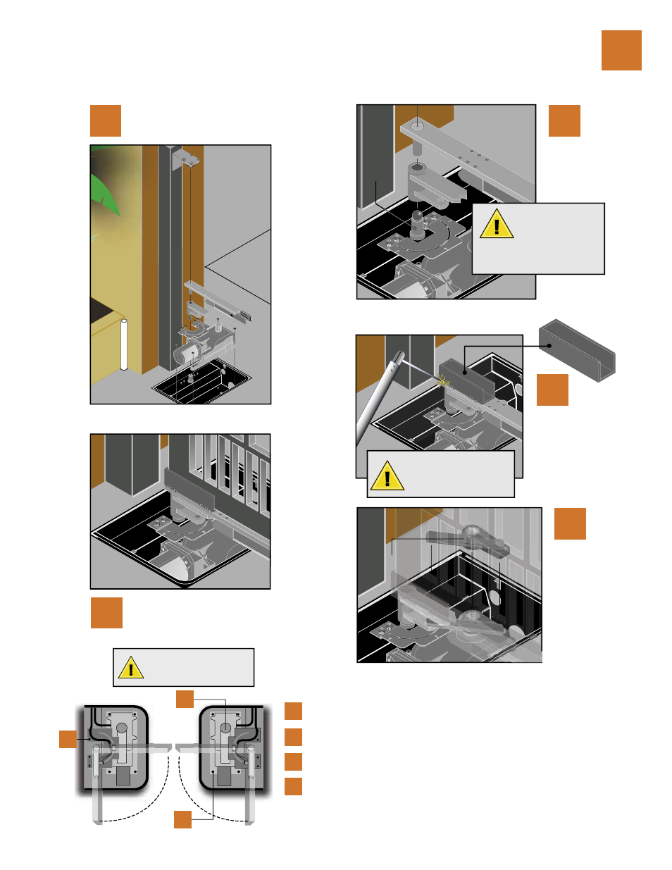
underground operator installation / gate mount
Reinstall the motor assembly.
1
Pivot and
Bearing
Weld the gate U-Channel
onto the gate support
bracket.
Weld on both sides.
Cover the components
avoiding weld scale
damage.
2
Install the crank
connecting assembly.
Gate MUST be
closed or at the
90 degree position
when installing the
crank connecting
assembly.
3
Install the gate on to the hinge and the
U-Channel, gate should swing freely
90 degrees.
4
Crank Connecting
Assembly
Grease the pivot,
and bearing and set
components in place
(see illustration for
assembly installation).
5
Operator confi guration
for biparting double door
installation.
The output shaft of the operator MUST be oriented on the outside of the gate, the motor/
gearbox and limit assembly may have to change.
Remove the four nuts holding the limit bracket, loosen the magnetic limit switches
and slide them 90°
Remove the four nuts holding the motor/gearbox, rotate the unit 180° and reinstall in the
mounting box with the limit assembly.
The LEFT HAND motor wires connect to the PRIMARY terminals. The RIGHT HAND
motor wires connect to the SECONDARY terminals. IMPORTANT: The left motor wires
BROWN and BLUE are interchanged on the right side motor to BLUE and BROWN.
1
3
4
1
2
3
2
NOTE: Locking bracket
and gate support should
be in place at 90 degrees.
DoorKing does
not provide the
U-CHANNEL, it
must be fabricated
according to existing
gate dimensions.