2 dip-switch settings – Controlled Products Systems Group 6002-080 User Manual
Page 23
21
3.2 DIP-Switch Settings
Whenever any programming or switch setting on the control board is changed, press the reset switch for new settings to take
effect.
Switch 1
Sets direction of the primary actuator so that the operator cycles open upon initial power up and open command. If the
actuator begins to cycle close upon initial power up and open command, turn power off and change the setting on this switch.
Switch 2
Sets direction of the secondary actuator so that the operator cycles open upon initial power up and open command. If
the actuator begins to cycle close upon initial power up and open command, turn power off and change the setting on this
switch.
Switch 3
Determines if the output of the loop detector (DoorKing loop detectors only) plugged into the EXIT port will be sent
directly to the microprocessor to open the gate, or if the output is directed to Terminal 4 where it can then be connected to other
input terminals.
Switch 4
Turns the auto close timer on or off. Maximum time that the close timer can be set for is approximately 23 seconds.
Switch 5
This switch sets the input at Terminal 8 to act as a normal reverse input or to act as a shadow input. A shadow input
will only hold the gate operator in the open position once it is in the full open position. A shadow input will not reverse the
direction of the gate actuator once it begins its close cycle.
Switch 6
Turns the gate overlap feature on or off. When turned ON, the Secondary actuator begins its cycle 1-2 seconds prior to
the Primary actuator, allowing the Primary gate to reach its full closed position 1-2 seconds before the Secondary gate. This
feature is useful when a magnetic lock is used to secure the gates.
Switch 7
Sets up the circuit board for single or dual (Primary / Secondary) gate operation.
Switch 8
Spare switch. Leave in the OFF position.
Switch 1 and 2
These work in conjunction with each other and determine when the relay on the board will be activated. This
relay can be used as a switch for various functions such as illuminating a warning light when the gate is moving, or turning on a
green light when the gate is full open. This relay is not available for these uses if it is being used for the shadow loop function.
Switch 3
Used for a maglock or a DK deadbolt lock.
Switch 4
Spare switch. Leave in OFF position.
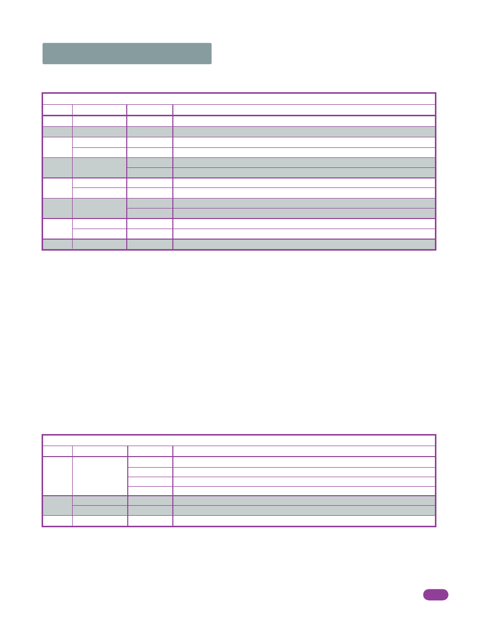
Switch
Function
Setting
Description
SW 1 (Top 8 Switches)
Primary
Secondary
Exit loop
Logic Output
OFF
ON (normal)
OFF
ON
OFF (normal)
ON
OFF
ON
Auto-Close
Timer
Reverse
Shadow
Overlapping
Gates
1
2
3
4
5
6
Direction-actuator should cycle open upon initial power up and open command.
Direction-actuator should cycle open upon initial power up and open command.
Terminal 4 is output from exit loop detector.
Terminal 4 is open command.
Auto-close timer is OFF. Manual input required to close gate.
Auto-close timer is ON. Adjustable from 1-23 seconds.
Terminal 8 is a standard Reverse input.
Terminal 8 is a Shadow reverse input.
Both actuators start at the same time.
Secondary actuator starts 1-2 seconds before primary actuator.
OFF
ON
Single
Dual
Switch must be OFF for single actuator.
Switch must be ON when (dual) actuators are used.
7-OFF
7-OFF
7-ON
7-ON
8-OFF
8-ON
8-OFF
8-ON
Relay activates when gate is fully open.
Relay activates when gate is not closed.
Relay activates when gate is opening and open.
Relay activates when gate is opening and closing.
Switch
Function
Setting
Description
SW 2 (Bottom 4 Switches)
Spare
Leave in the OFF position.
OFF
Relay
Operation
1 and 2
3
4
Spare
Leave in the OFF position.
OFF
8
7
1 second delay to disengage maglock.
4-5 seconds delay to retract dead-bolt.
ON
OFF
Maglock
DK Deadbolt Lock
6002-065-M-6-08