3 main terminal description – Controlled Products Systems Group 6002-080 User Manual
Page 18
16
6002-065-M-6-08
1
2
3
4
5
6
7 8
9 10 11 12 13 14 15 16 17 18 19 20
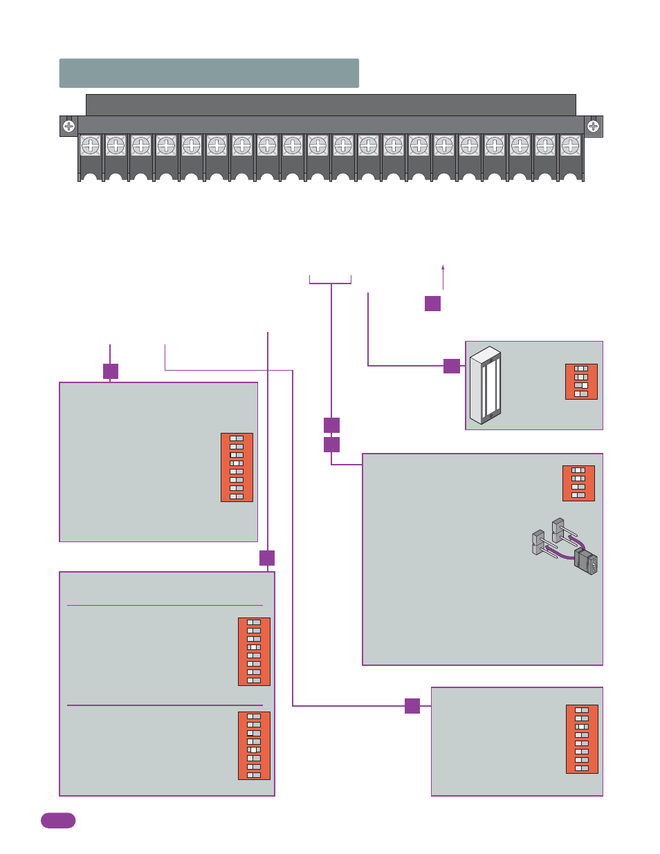
2.3 Main Terminal Description
24 V
AC INPUT
24 V
AC INPUT
24V COMMON
ALARM RESET
Not Used
12 VOL
T BA
TTER
Y
Not Used
DC LOCK POWER COMMON
24 VDC Maglock POWER
DR
Y RELA
Y CONT
ACT
DR
Y RELA
Y CONT
ACT
24V COMMON
REVERSE INPUT/SHADOW INPUT
24V COMMON
OPEN INPUT
24V COMMON
SINGLE BUTTON ACTIV
A
T
ION INPUT/
EXIT LOOP LOGIG OUTPUT
24V DC RADIO POWER ONL
Y
250 ma. maximum
RADIO RELA
Y -
SINGLE BUTTON ACTIV
A
T
ION INPUT
24V COMMON
Operation of relay is dependent on setting of
SW 2, switches 1 and 2. Relay contacts can
be set for Normally Open (NO) or Normally
Closed (NC) operation.
Contact rating is
1 amp maximum at 24 Volts.
1
ON
2
3
4
SW 2
•
Switch 1 OFF, Switch 2 OFF:
Relay activates when gate is OPEN.
•
Switch 1 OFF, Switch 2 ON:
Relay activates when gate is OPEN,
OPENING or CLOSING.
•
Switch 1 ON, Switch 2 OFF:
Relay activates when gate is OPEN or OPENING.
•
Switch 1 ON, Switch 2 ON:
Relay activates when gate is OPENING or CLOSING.
NO
NC
1
ON
2
3
4
SW 2
Maglock:
Switch 3 ON,
1 sec. delay
at start.
1
ON
2
3
4
5
6
7
8
SW 1
•
When gate is closed, input will open gate.
•
When gate is open and auto close
timer SW 1, switch 4 is turned ON,
input will re-set and hold timer.
•
When gate is open and auto close
timer SW 1, switch 4 is turned OFF,
input will close gate.
•
When gate is closing, input will
reverse gate.
•
lf SW 1, switch 3 is ON,
this input is identical to
Single Button Activation.
•
lf SW 1, switch 3 is OFF,
this terminal becomes the
logic output of the EXIT loop
detector.
1
ON
2
3
4
5
6
7
8
SW 1
•
When gate is closed, this input has no
affect on the gate operator.
•
When gate is open and auto close
timer SW 1, switch 4 is turned ON,
input will re-set and hold timer.
•
When gate is open and auto close
timer SW 1, switch 4 is turned OFF,
input will prevent gate from closing.
•
When gate is closing, input will
reverse gate if SW 1, switch 5 is OFF.
•
When gate is closing, input has no
affect on the gate operator if SW 1,
switch 5 is ON (set for shadow input).
1
ON
2
3
4
5
6
7
8
SW 1
1
ON
2
3
4
5
6
7
8
SW 1
4
8
2
15
12
10
11
DC power is not present on the board
until first initial cycle of gate.