2 dip-switch descriptions and functions – Controlled Products Systems Group 1150-080 User Manual
Page 21
1150-065-F-1-11
19
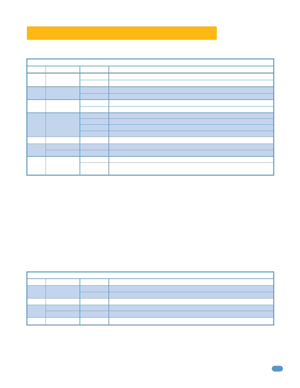
3.2 DIP-Switch Descriptions and Functions
The two DIP-switches located on the circuit board are used to program the operator to operate in various modes and to turn on
or off various operating features. Whenever a switch setting is changed, power to the operator must be turned OFF and then
turned back on for the new setting to take affect. Check and review ALL switch settings prior to applying power to the operator.
Switch 1
Sets direction of the operator so that the operator cycles open upon initial power up and open command. If the operator begins to
cycle close upon initial power up and open command, turn power off and change the setting on this switch.
Switch 2
Turns the auto close timer on or off. Maximum time that the close timer can be set for is approximately 23 seconds.
Switch 3
Determines if the output of the loop detector (DoorKing loop detectors only) plugged into the EXIT port will be sent directly to the
microprocessor of a single slide or overhead gate operator’s circuit board, or if the output is directed to the Main Terminal 4 where it can then
be connected with a secondary slide gate operator ONLY. Turn switch ON, Main Terminal 4 is not used for an overhead gate operator.
Switches 4-5
These work in conjunction with each other and determine when the relay on the circuit board will be activated. This relay can be
used as a switch for various functions such as illuminating a warning light when the gate is moving, or turning on a green light when the gate
is full open.
Switch 6
Spare switch, not used. Leave in OFF position.
Switch 7
Determines if an input to terminal 7 will reverse and open or stop then close a closing gate. If this switch is set to stop then close
(ON), input to terminal 7 will stop closing gate, once input is removed (cleared), the gate will continue to close. This is typically used to help
prevent tail-gating.
Switch 8
Turning quick-close on will cause the auto close timer to close the gate after 1 second, regardless of the timer’s setting. This will also
cause an opening gate to stop, then close when the reverse (loop) inputs have been cleared by vehicle no matter how far the gate has opened.
This feature helps prevent an unauthorized second vehicle from driving through a single authorized long open/close cycle for large gates.
Switch 1
This switch must be in the OFF position for normal operation. The self-test feature checks various functions of the operator. CAUTION
- Do not run self-test with the operator connected to the gate. The drive chain must be disconnected from the operator to run the self-test.
Switch 2
Spare switch, not used. Leave in OFF position.
Switch 3
Sets the circuit board to function with slide gate operators (switch OFF) or overhead gate operators (switch ON). This switch must be
left in the ON position for model 1150 Overhead Gate Operator.
Switch 4
Spare switch, not used. Leave in OFF position.
Switch
Function
Setting
Description
SW 1 (Top 8 Switches)
Change
Direction
EXIT Loop
Port
OFF
ON
OFF
OFF
ON
4-OFF
4-OFF
4-ON
4-ON
5-OFF
5-ON
5-OFF
5-ON
Auto-Close
Timer
Relay
Not Used
Reverse and Open
Stop then Close
Quick
Close
1
2
3
7
8
6
4 and 5
Changes open/close direction operator should cycle open upon initial power up.
Normal setting.
EXIT loop port output is sent to terminal 4 for secondary slide gate operator only.
Normal setting. EXIT loop port output is sent directly to circuit board.
Normal setting.
OFF
OFF
Not Used
Normal setting.
Not Used
Normal setting.
OFF
ON
OFF
ON
Auto-close timer is OFF. Manual input (push control button) required to close gate.
Auto=close timer is ON. Adjustable from 1-23 seconds.
Normal Setting. During close cycle, input to terminal 7 will reverse and open gate.
During close cycle, input to terminal 7 stops gate, after input removed, closes gate.
OFF
ON
Normal Setting. Normal gate operation.
Opening gate will stop, then close as soon as all reversing inputs (loops, beams)
have been cleared by vehicle regardless of how far the gate has opened.
Relay activates when gate is full open.
Relay activates when gate is not closed.
Relay activates when gate is opening and open.
Relay activates when gate is opening and closing.
Switch
Function
Setting
Description
SW 2 (Bottom 4 Switches)
Self Test
OFF
ON
1
2
3
4
Normal Setting.
Run self test - bench testing only. Operator must not be connected to gate!
Slide Gate
Overhead Gate
OFF
ON
Normal setting. Must be in the ON position for overhead gate operator.