3 adjust chain tension 1.4 attach gate bracket, 5 attach header bracket, Side view of gate opening alternate mounting – Controlled Products Systems Group 1150-080 User Manual
Page 11: Header, Header bracket assembly
1150-065-F-1-11
9
Top G
ate Rail
Header
2.5” Minimum
2.5” Minimum
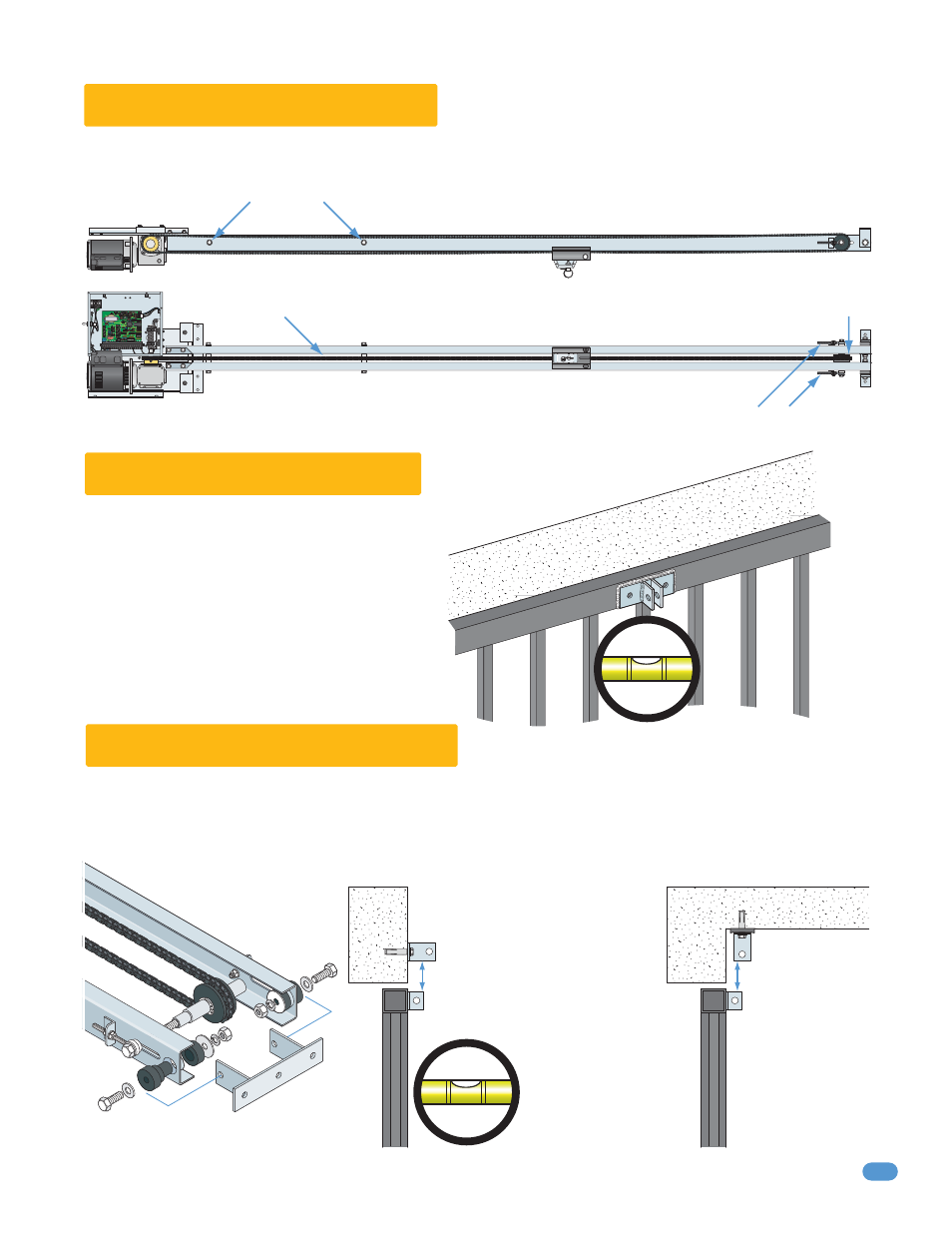
1.3 Adjust Chain Tension
1.4 Attach Gate Bracket
Do not overtighten chain. Make adjustments equally on both sides of rails. Chain will need final adjustment after operator has
been mounted. Chain will stretch over time and will need to be tightened.
Center the header bracket above the top of the gate bracket a minimum of 2.5 inches from the bottom of the header bracket.
Check the gate’s opening swing path, some gates will swing open higher than the bottom of the header and could hit the rails
if they are mounted too low. Header bracket must be securely mounted.
Install the gate bracket on the top rail of the gate by
bolting or welding. Bracket must be mounted level
and centered on gate!
Install the header bracket
centered above the gate
bracket with lag bolts,
anchor sleeves or welding.
Header Bracket must be
mounted level!
It is recommended
that the header
bracket be isolated
from the ceiling by
use of rubber shock
mount.
Do not let chain touch steel rail separators.
Chain must be centered between rails.
Return wheel must be centered between rails.
Chain tension adjustment. Adjust equally on both sides of rails.
Approximate chain tension, front rail removed for illustration.
1.5 Attach Header Bracket
Header
Side View of Gate Opening
Alternate Mounting
Gate Bracket
Header Bracket
Header Bracket Assembly
Header
Ceiling
Gate Bracket
Header Bracket
Check all local building codes and
ordinances to ensure compliance.
LIMIT
LIMIT
PA
R
T
TIME
DELA
Y
REV SENSE
CLOSE
REV SENSE
OPEN
1
ON
23
4
1
ON
23
45
67
8
NO
NC
EXIT
LOOP
REVERSE
LOOP
GA
TE FORCED