4 main terminal description – Controlled Products Systems Group 1150-080 User Manual
Page 16
1150-065-F-1-11
14
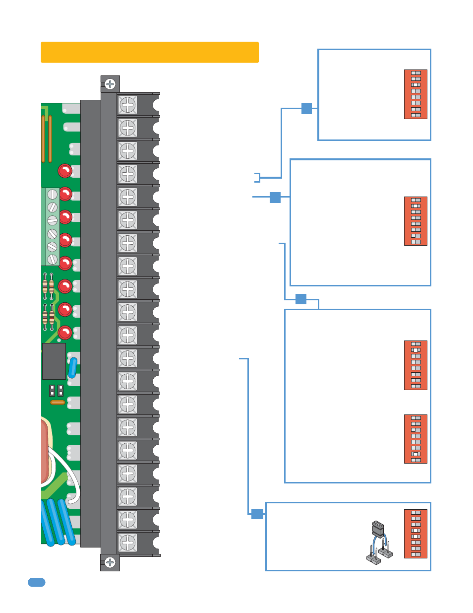
2.4 Main Terminal Description
1. LOW VOLTAGE COMMON
2. NOT USED
3. NOT USED
4. OPEN INPUT/
EXIT LOOP LOGIC OUTPUT
5. FULL OPEN/CLOSE INPUT
6. NOT USED
7. STANDARD REVERSE/STOP INPUT
8. OPEN INPUT
9. CLOSE INPUT
10. GATE TRACKER - DATA
11. GATE TRACKER - BUSY
12. DRY RELAY CONTACT
13. DRY RELAY CONTACT
14. 24 VAC 250ma Max.
15. NOT USED
16. MOTOR
17. MOTOR
18. 120 VAC HOT
19. 120 VAC NEUTRAL
20. EARTH GROUND
CHASSIS
GROUND
•
lf SW 1, switch 3 is ON,
this is an open input.
•
lf SW 1, switch 3 is OFF,
this terminal becomes the
logic output of the loop
detector plugged into the
exit loop plug (DoorKing
Loop Detectors Only).
•
Operation of relay is dependent on
setting of SW 1, switches 4 and 5.
Relay contacts can be set for
Normally Open (NO) or Normally
Closed (NC) operation.
Relay contact rating is 1 amp
maximum at 24-volts DC.
•
When gate is open and auto close
timer SW 1, switch 2 is turned ON,
input will re-set and hold timer.
•
When gate is open and auto close
timer SW 1, switch 2 is turned OFF,
input will close gate.
•
When gate is closing, input will
reverse gate.
•
When gate is open and auto close
timer SW 1, switch 2 is turned ON,
input will re-set and hold timer.
•
When gate is open and auto close
timer SW 1, switch 2 is turned OFF,
input will prevent gate from closing.
•
When gate is closing and SW 1,
switch 7 is turned OFF, input will
reverse gate.
•
When gate is closing and SW 1,
switch 7 is turned ON, input will stop
gate.
1
ON
2
3
4
5
6
7
8
1
ON
2
3
4
5
6
7
8
1
ON
2
3
4
5
6
7
8
1
ON
2
3
4
5
6
7
8
NO
NC
SW 1
SW 1
1
ON
2
3
4
5
6
7
8
SW 1
SW 1
SW 1
12
4
5
NO
NC
20
19
18
17
16
15
14
13
12
11
10
9
8
7
6
5
4
3
2
1
DoorKing 3-Button Control Station Only
DoorKing 3-Button Control Station Only
Radio Receiver Power and/or
Gate Tracker Only
•
When gate is closed or in the opening cycle,
this input has no effect on gate operator.
•
When gate is closed, this input will open
gate.
7