6 secondary entrapment protection wiring – Controlled Products Systems Group 1150-080 User Manual
Page 18
1150-065-F-1-11
16
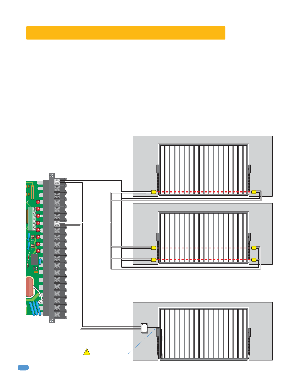
2.6 Secondary Entrapment Protection Wiring
Secondary entrapment prevention devices must be installed to insure a safe operating environment and reduce the risk of
personnel entrapment. Secondary entrapment prevention may be provided by a combination of both type sensors (UL 325 Type
B1 and B2).
Avoid interference
with gate hardware.
•
Use only UL listed (or equivalent) sensors.
•
Sensors shall be located where the risk of entrapment or obstruction exists, such as the perimeter reachable by a
moving gate or barrier. Additional sensors should be added for additional protection where entrapment zones exist.
Actual placement of sensors is dependent on the installation requirements.
•
Inputs from sensors to circuit board are Normally Open (NO).
•
Disconnect power to gate operator before installing the sensors.
•
Photo-cell should be placed so that an entrapment cannot occur at the lower travel of the gate. Do not place the
photo-cell so high that a person could be trapped under the gate without activating the photo-cell.
•
If high bed vehicles access the gate, a second photo-cell should be placed so that the photo-beam cannot scan
under the vehicle.
•
Photo-cells may require separate
power depending on model used.
•
Hardwired contact sensors must be located and wiring arranged so that the communication
between the sensor and the gate operator is not subjected to mechanical damage.
•
Additional contact sensors should be added where multiple entrapment zones may exist.
Non-Contact Sensor (Type B1)
Contact Sensor (Type B2)
NO
NC
20
19
18
17
16
15
14
13
12
11
10
9
8
7
6
5
4
3
2
1
Junction
Box
Com
N. O.
High Bed Vehicles (Multiple Beams)
Typical Vehicles (Single Beam)