Appendix e. troubleshooting, Table e1, Table e2 – CTI Products EXB-IP Ethernet System Extender User Manual
Page 47: Table e3, Ppendix, Roubleshooting
CTI Products, Inc.
EXB-IP User Guide
Appendix E - Troubleshooting
47
A
PPENDIX
E.
T
ROUBLESHOOTING
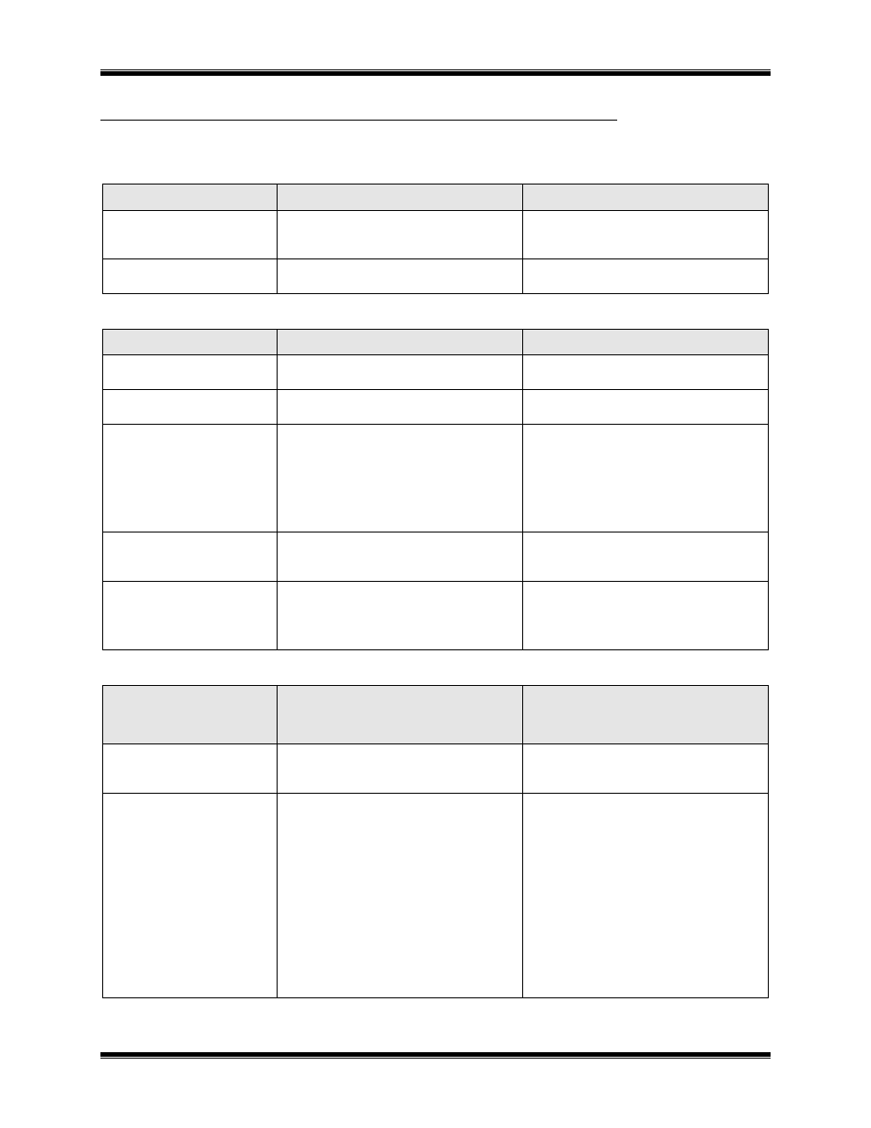
Table E1
If the PWR LED . . .
REASON
CORRECTIVE ACTION
Is always illuminated.
Normal operation indicating that EXB
module is receiving proper DC input
power.
Go to next Table.
Does not illuminate.
EXB module is not receiving DC input
power.
Check for proper voltage at “DC IN”
connector (10-32VDC).
Table E2
If the ERR LED . . .
REASON
CORRECTIVE ACTION
Is always off.
Normal operation indicating no error
condition was detected.
Go to next Table.
Occasionally blinks on, then
off.
Normal operation when “CSVC” button or
“RSVC” button is pressed.
Go to next Table.
Flashes slowly, at a rate of
once every 2 seconds.
The Router Neurons are unconfigured.
Use LonScrpt or NODEUTIL to change the
mode/state to ‘Configured’ and ‘On-
line’,
or
Use SETRTR2 –F to configure the
router to Factory default conditions
(Repeater Mode).
Flashes quickly, at a rate of
once every second.
The Control Neuron Processor detects
missing IP address information.
Use EXB-IP Config to update the IP address
parameters. (See Installation section
for instructions.)
Is always illuminated.
Router module, or Control Neuron
Processor, or Microprocessor is not
functioning.
Call CTI Products, Customer Support
(+1-513-595-5900), to arrange to
return module for evaluation/repair.
Table E3
If the ETH TX LED (on
local EXB-IP module)
. . .
REASON
CORRECTIVE ACTION
Occasionally blinks on, then
off.
Normal operation indicating a message
packet has been transmitted from the
Ethernet port.
Go to next Table.
Does not illuminate when
“RSVC” button on local
EXB-IP module is
pressed.
Ethernet port is not terminated correctly to
the IP network.
a.
Verify that OPTION switch positions 7
and 8 are set correctly for the Ethernet
connector being used. See
I
NSTALLATION
section.
b.
Verify that the cable from EXB-IP
module Ethernet port is terminated
correctly to IP network. Check the
‘connection’ LED that is found near
each port on most IP interconnect
devices.
c.
Verify that the correct cross or straight-
through cable is being used. See
“Appendix F. IP Addresses”.