Appendix c. connector details, Dc in connector, Network connectors – CTI Products EXB-IP Ethernet System Extender User Manual
Page 44: Rj45 connectors, Position screw-terminal, Ppendix, Onnector, Etails
CTI Products, Inc.
EXB-IP User Guide
Appendix C - Connector Details
44
A
PPENDIX
C.
C
ONNECTOR
D
ETAILS
DC IN Connector
Connector type:
2.5 x 5.5 mm coaxial
Mating Connector:
Switchcraft 760 or equivalent
Connector pinout:
CTI Products, Inc. standard power
supply is wired with center pin positive,
EXB module can accept either pin
positive, polarity routing is provided
internal.
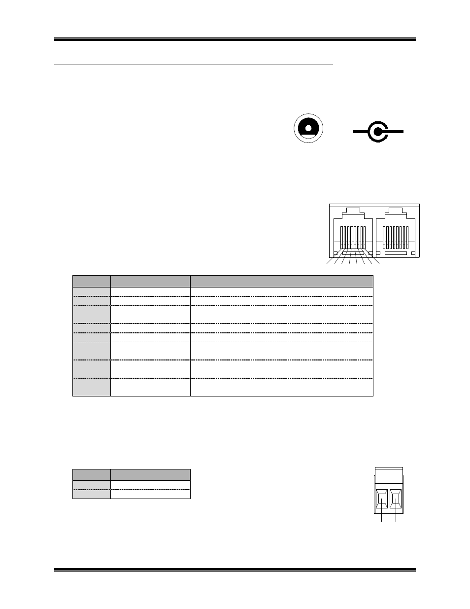
NETWORK Connectors
RJ45 Connectors:
Pins 1 and 2 of both RJ45 connectors as well as the screw-terminal connector
are all wired in parallel.
Connector Type:
Standard RJ45 telephone connector, 8 position 8
contact.
Pin
Function
Notes
1
Network
Network connection is NOT polarity sensitive
2
Network
Pins 1,2 of IN and OUT connectors tied parallel
3
No Connection
Note 1
Pin 3 of IN and OUT connectors tied together
4
No Connection
Pin 4 of IN and OUT connectors tied together
5
No Connection
Pin 5 of IN and OUT connectors tied together
6
No Connection
Note 2
Pin 6 of IN and OUT connectors tied together
7
No Connection
Note 2
Pin 7 of IN and OUT connectors tied together
8
No Connection
Note 1
Pin 8 of IN and OUT connectors tied together
Note 1: May have + DC power on this pin from other MCN modules.
Note 2: May have - DC power on this pin from other MCN modules.
2-Position Screw-Terminal:
Mating Connector:
Weidmuller 128176
Pin
Function
1
Network
2
Network
Note that this connector is normally not used in MCN networks.
+
-
Polarity
DC IN
Front View
NETWORK
OUT
IN
1
2
3
4
5
6
7
8
NETWORK
1
2