Front panel, Mcn network note 1, Mcn network note 2 – CTI Products EXB-IP Ethernet System Extender User Manual
Page 10: Reset button, Mcn network connections, Csvc button identifies control processor, Ront, Anel, Figure 3 exb-ip module front panel
CTI Products, Inc.
EXB-IP User Guide
Introduction
10
F
RONT
P
ANEL
1
2
3
4
5
9
8
7
6
PWR
WINK
NETWORK
OUT
ASYNC
NETWORK
IN
ERR
CSVC
RSVC
RESET
ETH TX
ETH RX
ACT
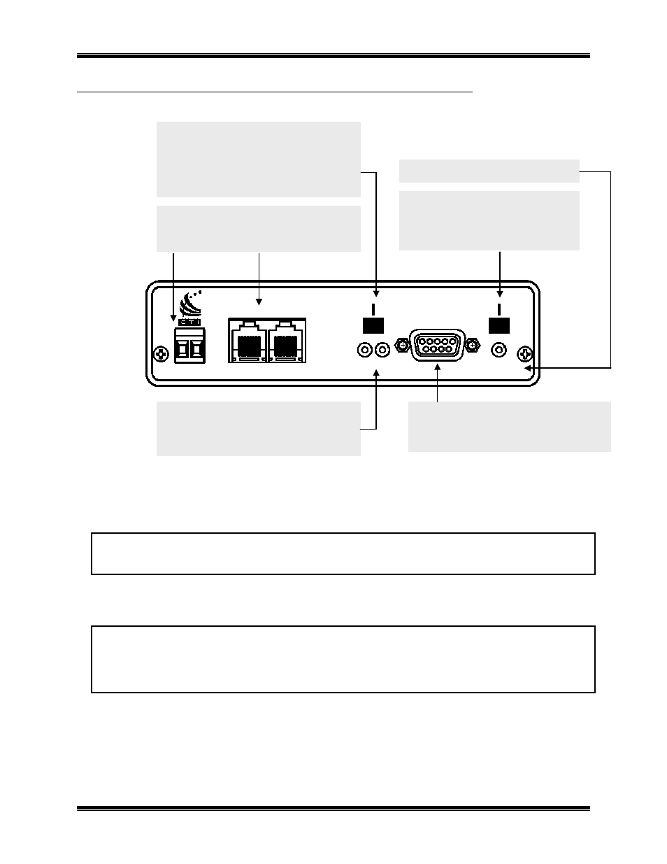
Figure 3 EXB-IP module Front Panel
MCN Network Note 1
Unlike most other MCN modules, the EXB-IP module does not inject power into the Network Out connector. It
also does not use any DC power from the Network In connector. All 8 pins on the Network In & Out connectors
are paralleled, so that any power from other modules will be passed through.
MCN Network Note 2
Although the MCN Network connectors are RJ-45s, THEY ARE NOT ETHERNET CONNECTORS. Because
the MCN network connectors on the front of the modules may have DC power on them from other MCN devices,
DO NOT CONNECT THE NETWORK IN OR OUT CONNECTORS TO ETHERNET PORTS. THIS CAN
DAMAGE THE ETHERNET DEVICE. The Ethernet cable should be connected to the 10BASE-T connector on
the rear of the EXB module.
ETH TX LED Indicates when a packet has been
transmitted on the Ethernet port
WINK LED
Normally not used.
May be winked during Custom
Configuration to identify a unit.
ETH RX LED Indicates when a packet has been
detected on the Ethernet port
MCN NETWORK Connections
RJ-45 Normal Network connection.
Screw Terminals not normally used.
*** See MCN Network Notes 1 & 2***
ASYNC Connector
Used with PC running EXB Config
to access IP address parameters
RESET Button
Buttons for use with Custom Configuration
Press only when requested.
CSVC Button Identifies Control Processor
RSVC Button Identifies internal Router
PWR LED Indicates correct input power
ERR LED
Indicates an error condition
(see below)
ACT LED
Indicates MCN packet being
passed through unit.