CONTREX ML-Drive User Manual
Page 44
3 - 10
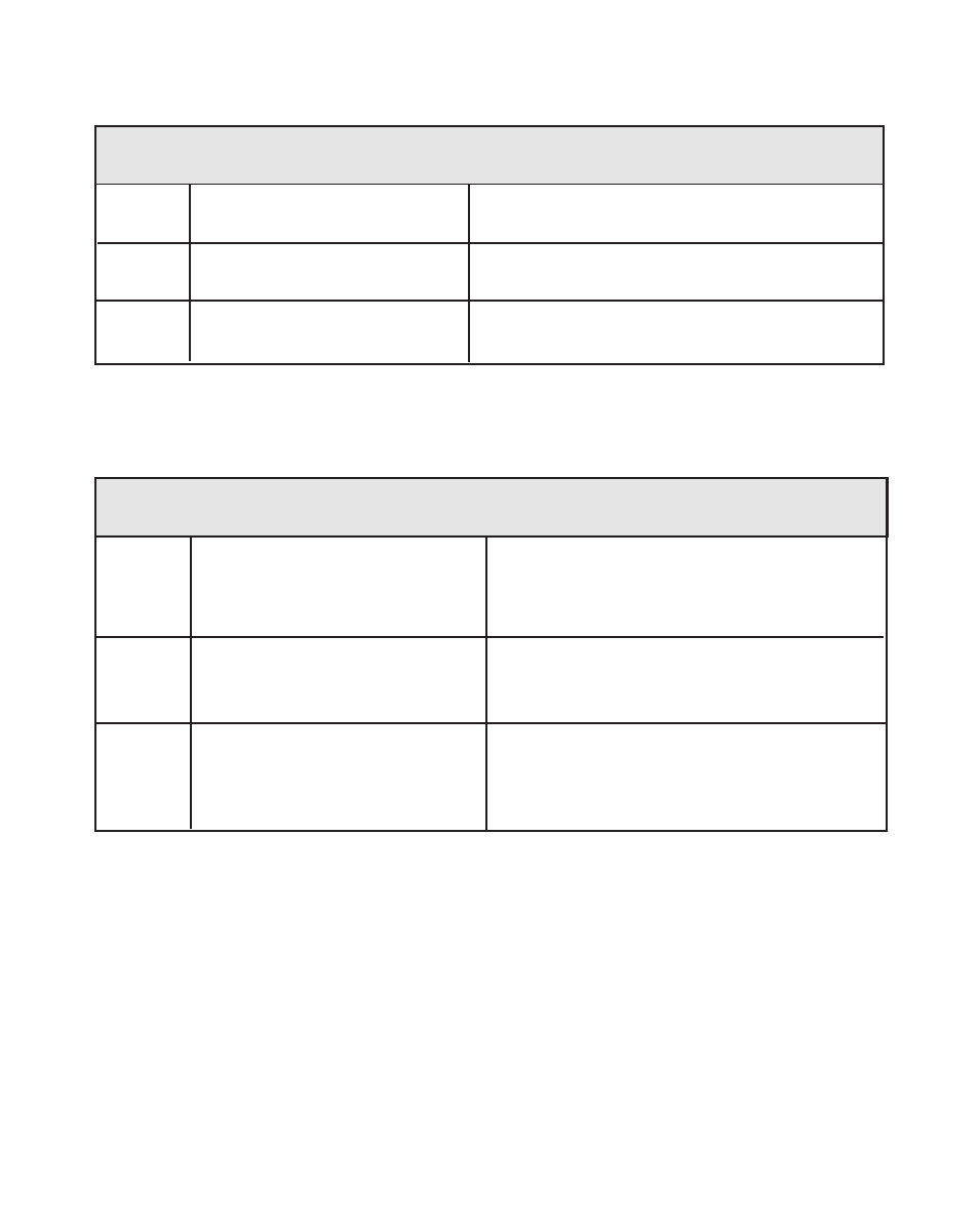
Table 3-4 Default Master Scaling Control Parameters
CP
Parameter Name
Parameter Value
CP-34
Max RPM Feedback
2000
CP-31
PPR Feedback
60
CP-20
Master Engineering Units
2000
Table 3-5 Entering Master Scaling Control Parameters
CP
Parameter Name
Parameter Value
CP-34
Max RPM Feedback
CP-31
PPR Feedback
CP-20
Master Engineering Units
Enter the maximum desired RPMs,
measured at the sensor shaft.
Enter the number of gear teeth or
encoder lines on the sensor per one
revolution (pulses per revolution).
Enter the Master Engineering Units
value if the system were to operate at
the maximum desired RPMs entered in
CP-34.
Now that your scaling has been established, you can enter a value for Master
Setpoints 1 and 2. The value that you enter for a setpoint is the Engineering Units
(E.U.s) that you want to operate your system at.
The factory default Control Parameters for Master Setpoint 1 and 2 are set at “0”. To
modify these default parameters, refer to Table 3-6. You can toggle between the two
setpoints, if you have wired the Setpoint Select accordingly. Setpoint Select (located
at J4 pins 13, 14) determines which of the two setpoints is active (refer to
Setpoint
Select
on page 2-12). If you are uncertain how to enter a Control Parameter, review
the
Operations: Keypad
section, page 3-3.