Outputs, Outputs -13 – CONTREX ML-Drive User Manual
Page 27
2 - 13
OUTPUTS
NOTE: The installation of this motor control must conform to area and local electrical
codes. See
The National Electrical Code
(NEC,) Article 430 published by the
National Fire Protection Association, or
The Canadian Electrical Code
(CEC).
Use local codes as applicable.
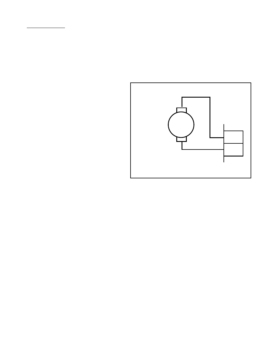
Drive Output
(J2 pins 1, 2)
Connect the Drive Output
(J2 pins 1, 2) to the armature leads
(A1 and A2) of your permanent
magnet, DC motor. If you reverse the
armature leads, then the direction of
the motor rotation also reverses.
Figure 2-14 Drive Output
Drive Enable
(J4 pin 16)
The Drive Enable output is activated (driven low) when the ML-Drive is signaling a
nonzero speed to the motor, as defined by Drive Enable Logic (CP-74) The Drive
Enable output is driven high (relay deactivated) after Power Up and during R–Stop and
F–Stop. See Figure 2-15. Refer to
Operations: Logic Control, Logic Output,
page 3-37 for details.
NOTE: This is an open-collector relay driver. For specification details, see
References:
Appendix A
-
ML-Drive Specifications,
page A-1. Use an external DC power
supply to power the relays. Free-wheeling diodes are incorporated internally in
the ML-Drive and do not need to be added externally.
1
2
J2
A1
A2
+
–
DC PM
Motor