Alarm, Warning, Auxiliary dc power – CONTREX ML-Drive User Manual
Page 28
2 - 14
Alarm
(J4 pin 17)
By entering alarm Control Parameters, you can establish circumstances under which
the ML-Drive will alert you to potential operating problems. The alarm can be wired to
activate a warning light, a warning sound, or to shut down the system under specified
conditions. Alarm Format (CP-10) determines which alarm conditions will activate the
Alarm output, using the values that are entered in Low Alarm (CP-12), High Alarm
(CP-13), Ramped Error (CP-14) and Scaled Error (CP-15). See Figure 2-15. Refer to
Operations: Logic Control, Logic Output,
page 3-37 for details.
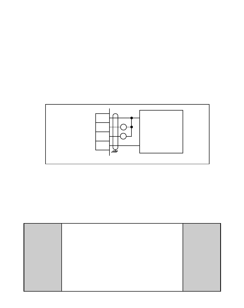
NOTE: This is an open-collector relay driver. Use an external DC power supply to
power the relays. Free-wheeling diodes are incorporated internally in the
ML-Drive and do not need to be added externally.
15
16
17
18
J4
EXTERNAL
DC
POWER
SUPPLY
(50V Max)
R1
R2
+V_DO
Drive Enable
Alarm
Common
+
–
WARNING
Do not exceed
the maximum current output of
150 mA for +5 VDC.
Exceeding the maximum
current output
can damage the ML-Drive.
Figure 2-15 Drive Enable and Alarm Outputs
Auxiliary DC Power
(J3 pin 1, 2)
The 5 volt output (J3 pin 1) is a DC regulated output that can be used to power
encoders or other auxiliary equipment that is used in conjunction with the ML-Drive. If
this output is used, it will nullify optical isolation.