Operation 79, Figure 4-6 parameter table of the positioner – Cashco Siemens PS2 I/P User Manual
Page 79
Operation
79
SIPART PS2 Manual
A5E00074631-01
(example)
3.YWAY
2)
1)
4.INITA
5.INITM
6.SCUR
10.TSUP
11.TSDO
12.SFCT
13.SL0
14.SL1
usw. bis
32.SL19
33.SL20
9.SPRE
8.SPRA
7.SDIR
3)
2.YAGL
1.YFCT
34.DEBA
35.YA
36.YE
39.YCLS
40.YCDO
41.YCUP
37.YNRM
38.YDIR
5)
5)
43.BIN2
44.AFCT
45.A1
46.A2
42.BIN1
4)
4)
55.PRST
48. TIM
47. FCT
49. LIM
50. STRK
51. DCHG
52. ZERO
53. OPEN
54. DEBA
OFF
OFF
OFF
0,0 bis 100,0
0,0 bis 100,0
on
uP
doWn
StoP
-on
-uP
-doWn
-StoP
on
bLoc1
bLoc2
uP
doWn
StoP
-on
-uP
-doWn
-StoP
no
Strt
oCAY
Auto
0,0 bis 100,0
OFF
1 bis 1.00E9
OFF
1 bis 1.00E9
OFF
0,0 bis 100,0
OFF
0,0 bis 100,0
OFF
0,0 bis 10,0
Auto
0 bis 100
noini | no / ###.# | Strt
0 MA
4 MA
riSE
FALL
riSE
FALL
Auto
0 bis 400
0 bis 400
Lin
1 - 33
FrEE
n1 - 33
1 - 50
n1 - 50
1- 25
n1 - 25
0,0 bis 100,0
25 | 30 | 35
40 | 50 | 60 | 70 | 90 | 110 | 130
5 | 10 | 15 | 20
(kurzer Hebel 33°)
(kurzer Hebel 90°)
(langer Hebel 90°)
Auto
0,1 bis 10,0
0,0 bis 100,0
0,0 bis 100,0
0,0 bis 100,0
0,0 bis 100,0
0,0 bis 100,0
0,0 bis 100,0
MPOS
FLOW
no
uP
do
uP do
OFF
OFF
noini | no / ###.# | Strt
%
%
%
%
%
%
%
s
%
%
%
%
%
s
s
%
%
mm
33°
WAY
0.0
5.0
usw. bis
95.0
100.0
Lin
0
0
riSE
riSE
OFF
no
no
4 MA
no
MPOS
100,0
99,5
0,0
0,0
100
0,5
Auto
90,0
10,0
OFF
OFF
OFF
Auto
Auto
OFF
OFF
OFF
OFF
OFF
OFF
OFF
90°
33°
Parameter name
Display
Function
Parameter values
Unit
Factory setting
Customer setting
Rated angle of rotation of feedback
Type of actuator
turn (part-turn actuator)
WAY (linear actuator)
LWAY (linear actuator
without sine correction)
ncSt (part-turn actuator with NCS)
-ncSt (ditto, inv. direction of action
Set transmission ratio selector (7) appropriately
(see view of device)
Degrees
Stroke range (optional setting)
When used, the value must correspond with
the set of the leverage ratio on the actuator
Driver pin must be set to the value of the actuator
travel or, if this value is not scaled, to the next
larger scale value.
Initialization (automatically)
Initialization (manually)
Setpoint ramp up
Setpoint direction
0 to 20 mA
4 to 20 mA
rising
falling
Current range of setpoint
Setpoint for start of split range
Setpoint for end of split range
Setpoint ramp down
Setpoint function
Linear
Equal-percentage 1:25, 1:33, 1:50
Inverse equal-percentage
Freely adjustable
1:25, 1:33, 1:50
Setpoint turning point at 0%
5%
to
95%
100%
Dead zone of controller
Start of manipulated variable limiting
End of manipulated variable limiting
Standardization of
manipulated variable
To mech. travel
To flow
None
Only message
Block configuring
Block configuring and manual
Drive valve to position up
Drive valve to position down
Block movement
Function of BI 1
Tight closing with
manipulated variable
Value for tight closing, bottom
Value for tight closing, top
Direction of manipulated
variable for display
Without
Top only
Bottom only
Top and bottom
Rising
Falling
NO
c
o
nt
a
ct
NO c
o
nt
a
ct
None
Only message
Drive valve to position up
Drive valve to position down
Block movement
Alarm function
Without
A1=min. A2=max
A1=min. A2=min
A1=max. A2=max
Response threshold of alarm 1
Response threshold of alarm 2
no
rm
a
l
no
rm
a
l
Function of BI 2
on fault
Fault + not automatic
Fault + not automatic + BI
("+" means logical OR operation)
Monitoring time for fault message
“control deviation”
Preset (factory setting)
"no" nothing activated
"Strt" start of factory setting after pressing key for 5 s
"oCAY" display following successful factory setting
CAUTION: preset results in "NO INIT"
Response threshold for fault message
“control deviation”
Limit for stroke integral
Function of alarm output
in
ve
rt
e
d
in
ve
rt
e
d
N
C
co
n
ta
c
t
N
C
co
n
ta
ct
Limit for direction change
Limit for end stop monitoring, bottom
Limit for end stop monitoring, top
Limit for dead zone monitoring
If "turn" is selected, you cannot set 33°
Parameter does not appear if 1.YFCT=turn has been selected
Turning points only appear wih selection 12.SFCT = FrEE
Alternatively "no" if initialization has not yet been carried out
NC contact means:
NO contact means:
Normal means: High level without fault
Inverted means: Low level without fault
1)
2)
3)
4)
5)
6)
action with opened switch or Low level
action with closed switch or High level
1)
2)
3)
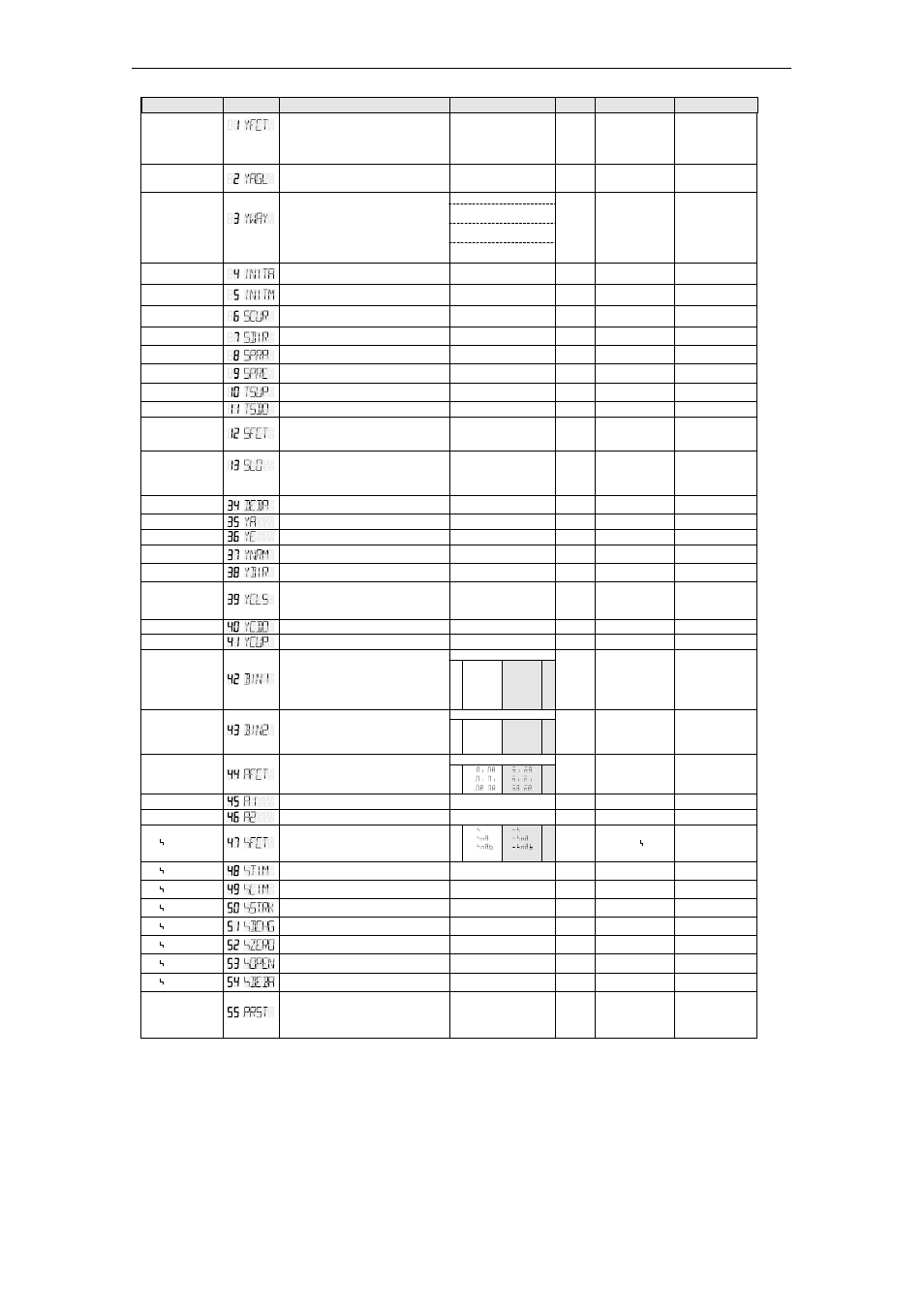
Figure 4-6
Parameter table of the positioner