Cashco 764T Temperature Controller User Manual
Model 764t, Pneumatic temperature controllers
INSTALLATION, OPERATION, & MAINTENANCE MANUAL
SECTION I
I. DESCRIPTION AND SCOPE
The Model 764T is a temperature controller with an integral, rigid insertion bulb used for sensing temperature, and
outputting a pneu mat ic signal proportional to the deviation from the setpoint.
This IOM-764T does not cover use of oxygen as the "instrument air" fl uid. Such an application is outside the scope
of this IOM.
With proper materials and pipe sizes, the 764T can be used to measure the tem per a ture of liquid, gaseous, or va por
service. The installation of the thermal bulb can be direct or in di rect using a thermal well. Refer to Technical Bulletin
764T-TB for de sign and selection rec om men da tions.
IOM-764T
12/13
Abbreviations Utilized:
IAS - Instrument Air Supply
ES - Electrical Supply
CW - Clockwise
SIG - Signal
TC - Temperature Control valve
CCW - Counter Clockwise
P/P - Pneumatic-to-Pneumatic
P1 - Inlet Pressure
REV - Revolution or Reverse
TC - Temperature Controller
P2 - Outlet Pressure
DIR - Direct
TI - Temperature Indicator
TR - Condensate Trap
FS - Flow Switch
SRV - Safety Relief Valve
PB - Proportional band
SOV - Solenoid Valve
SECTION II
II. INSTALLATION
Location of the thermal bulb into the medium
being con trolled is crit i cal.
Always insert the maximum bulb length into
the medium.
Always locate the bulb at a point downstream
of a heat exchanger to assure a near-equal
dis tri bu tion of the tem per a ture across the con-
tainment cross-section.
Always locate the control valve doing the tem-
per a ture control no further than 6-10 feet (2-3
meters) away from the controller when the
control valve does not have a po si tion er.
Do not use a thermal well unless the Owner's
process conditions, safety considerations or
main te nance pro ce dures require such; a ther mal
well enters an extra time response delay (i.e.
reduction in sensitivity) to the closed loop.
If a thermal well is required,to maximize heat
transfer effi ciency, locate on the top of a pipe
(vertical or at a 45° angle), duct, or at a 45°
angle to a vertical wall or horizontal top, when
possible, to allow fi lling of "void space" in well
with a suitable liquid heat transfer medium.
(See Figure's 4 and 5).
If a thermal well must be installed in a hor i zon tal
ori en ta tion, attempt to "pack" the "void space"
with steel or SST wool at bulb in ser tion. Use of
the well packing will in crease thermal effi ciency
(re duce time con stants) above that of a "dead
air" space in the "void space"; i.e. dead air space
acts as an "in su la tor" to heat transfer.
f.
a.
b.
c.
d.
e.
MODEL 764T
PNEUMATIC TEMPERATURE CONTROLLERS
1
.
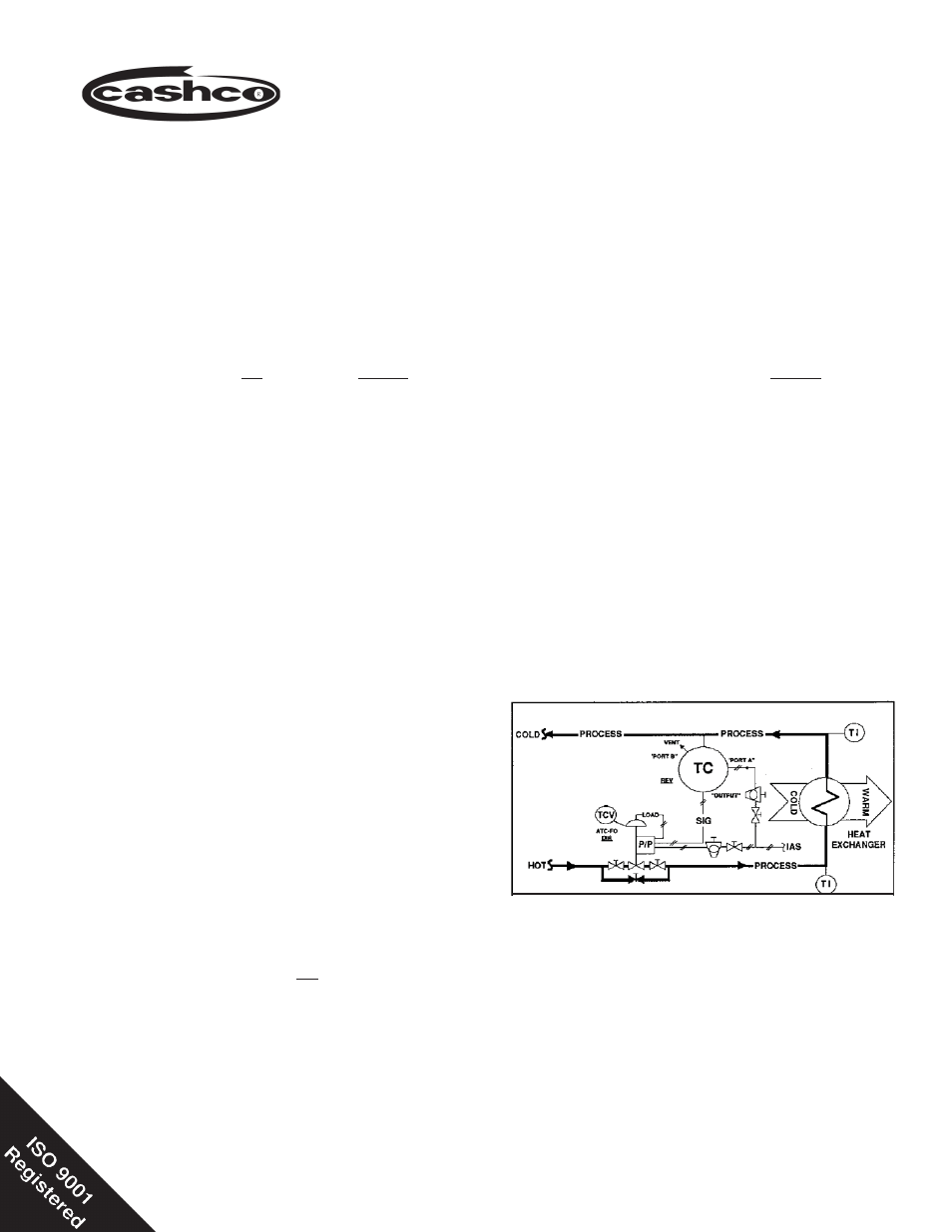
Figure 1: Typical Direct Cooling Application