Global Specialties PB-507 - Manual User Manual
Page 18
18
Figure 10
Description
PB-507 provides 8 logic debounced outputs with 2 user selectable logic families:
CMOS and TTL. Each of the logic switches can be switched separately between
logic high (red) and logic low (green) by pressing the buttons S7…S0. When
CMOS is selected, the high level is determined by the +V voltage set for the DC
power supply.
The logic family (TTL or CMOS) can be selected using the TTL/CMOS button.
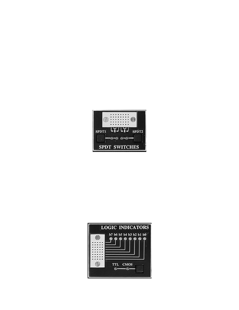
6.7 SPDT switches
Front-panel controls
Figure 11 shows the SPDT switches controls on the front panel of the trainer.
Figure 11
Description
Two single pole, double throw (SPDT) switches are provided for general switching
functions. Two LEDs for each switch are used to signal the current state of the
switch.
6.8 Logic indicators
Front-panel controls
Figure 12 shows the Logic indicators controls on the front panel of the trainer.
- 1523 - Data Sheet (1 page)
- 1523 - Manual (16 pages)
- 1522 - Data Sheet (2 pages)
- 1522 - Manual (13 pages)
- 9004 - Data Sheet (2 pages)
- PRO-50A - Data Sheet (1 page)
- PRO-1000 - Data Sheet (4 pages)
- PRO-1000 - Manual (18 pages)
- PB-204 - Data Sheet (2 pages)
- PB-204 - Manual (12 pages)
- PB-203A - Data Sheet (2 pages)
- PB-203A - Manual (12 pages)
- PB-507 - Data Sheet (2 pages)
- PB-505 - Manual (16 pages)
- PB-505 - Data Sheet (2 pages)
- PB-503C - Manual (16 pages)
- PB-503C - Data Sheet (2 pages)
- PB-503 - Manual (15 pages)
- PB-503 - Data Sheet (2 pages)
- PB-500 - Manual (12 pages)
- PB-500 - Data Sheet (2 pages)
- PB-501 - Manual (11 pages)
- PB-501 - Data Sheet (2 pages)
- PB-502 - Manual (16 pages)
- PB-502 - Data Sheet (2 pages)
- DL-030 (2 pages)
- DL-020 (2 pages)
- DL-010 (2 pages)
- PB-60 (1 page)
- PRO-S-LAB (8 pages)
- 3600 (37 pages)
- 2001A (11 pages)
- 4005 - Data Sheet (3 pages)
- 4005 - Manual (27 pages)
- RDB-10 - Data Sheet (1 page)
- RDB-10 - Manual (1 page)
- RC-10 - Data Sheet (2 pages)
- CDB-10 - Data Sheet (1 page)
- CDB-10 - Manual (1 page)
- 1305 - Data Sheet (2 pages)
- 1305 - Manual (9 pages)
- 1302B - Data Sheet (2 pages)
- 1310 (18 pages)
- 1332A (11 pages)